0 lm63 registers, Fan control registers – Rainbow Electronics LM63 User Manual
Page 17
2.0 LM63 Registers
(Continued)
Fan Control Registers
(Continued)
Address
Hex
Read/
Write
Bits
POR
Value
Name
Description
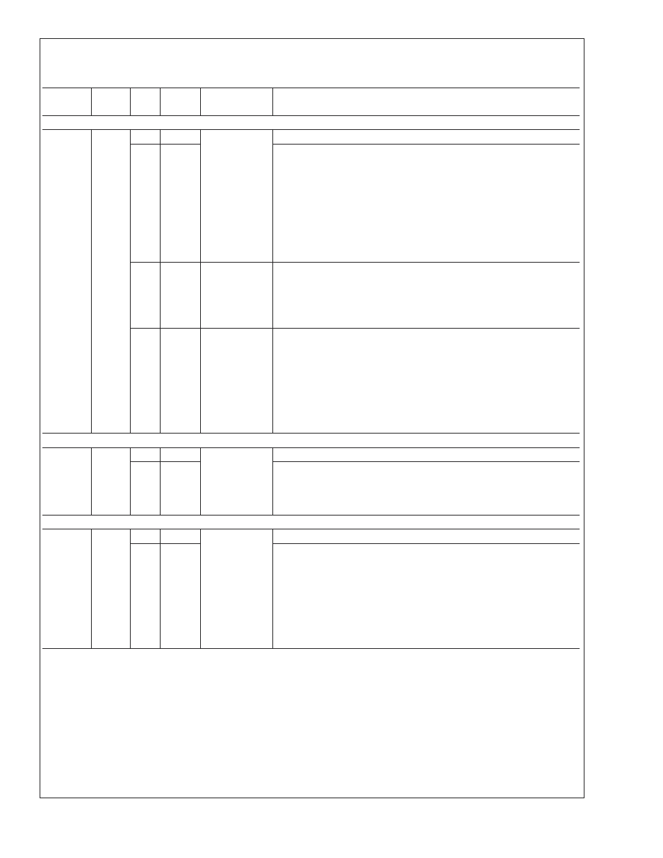
4B
HEX
FAN PWM AND TACHOMETER CONFIGURATION REGISTER
4B
R/W
7:6
0
Fast
Tachometer
Spin-Up
These bits are unused and always set to 0
5
1
If 0, the fan spin-up uses the duty cycle and spin-up time, bits 0–4.
If 1, the LM63 sets the PWM output to 100% until the spin-up times out
(per bits 0–2) or the minimum desired RPM has been reached (per the
Tachometer Setpoint setting) using the tachometer input, whichever
happens first. This bit overrides the PWM Spin-Up Duty Cycle register
(bits 4:3) — PWM output is always 100%. Register x03, bit 2 = 1 for
Tachometer mode.
If PWM Spin-Up Time (bits 2:0) = 000, the Spin-Up cycle is bypassed,
regardless of the state of this bit.
4:3
11
PWM
Spin-Up
Duty Cycle
00: Spin-Up cycle bypassed (no Spin-Up), unless Fast Tachometer
Terminated Spin-Up (bit 5) is set.
01: 50%
10: 75%–81% Depends on PWM Frequency. See Applications Notes.
11: 100%
2:0
111
PWM
Spin-Up
Time
000: Spin-Up cycle bypassed (No Spin-Up)
001: 0.05 seconds
010: 0.1 s
011: 0.2 s
100: 0.4 s
101: 0.8 s
110: 1.6 s
111: 3.2 s
4D
HEX
FAN PWM FREQUENCY REGISTER
4D
R/W
7:5
000
PWM
Frequency
These bits are unused and always set to 0
4:0
10111
The PWM Frequency = PWM_Clock / 2n, where PWM_Clock = 360
kHz or 1.4 kHz (per the PWM Clock Select bit in Register 4A), and n =
value of the register. Note: n = 0 is mapped to n = 1. See the
Application Note at the end of this datasheet.
4C
HEX
PWM VALUE REGISTER
4C
Read
(Write
only if
reg
4A bit
5 = 1.)
7:6
00
PWM
Value
These bits are unused and always set to 0
5:0
000000
If PWM Program (register 4A, bit 5) = 0 this register is read only and
reflects the LM63’s current PWM value from the Lookup Table.
If PWM Program (register 4A, bit 5) = 1, this register is read/write and
the desired PWM value is written directly to this register, instead of
from the Lookup Table, for direct fan speed control.
This register will read 0 during the Spin-Up cycle.
See Application Notes section at the end of this datasheet for more
information regarding the PWM Value and Duty Cycle in %.
LM63
www.national.com
17