Lm63 register descriptions in functional order, Fan control registers, 0 lm63 registers – Rainbow Electronics LM63 User Manual
Page 16
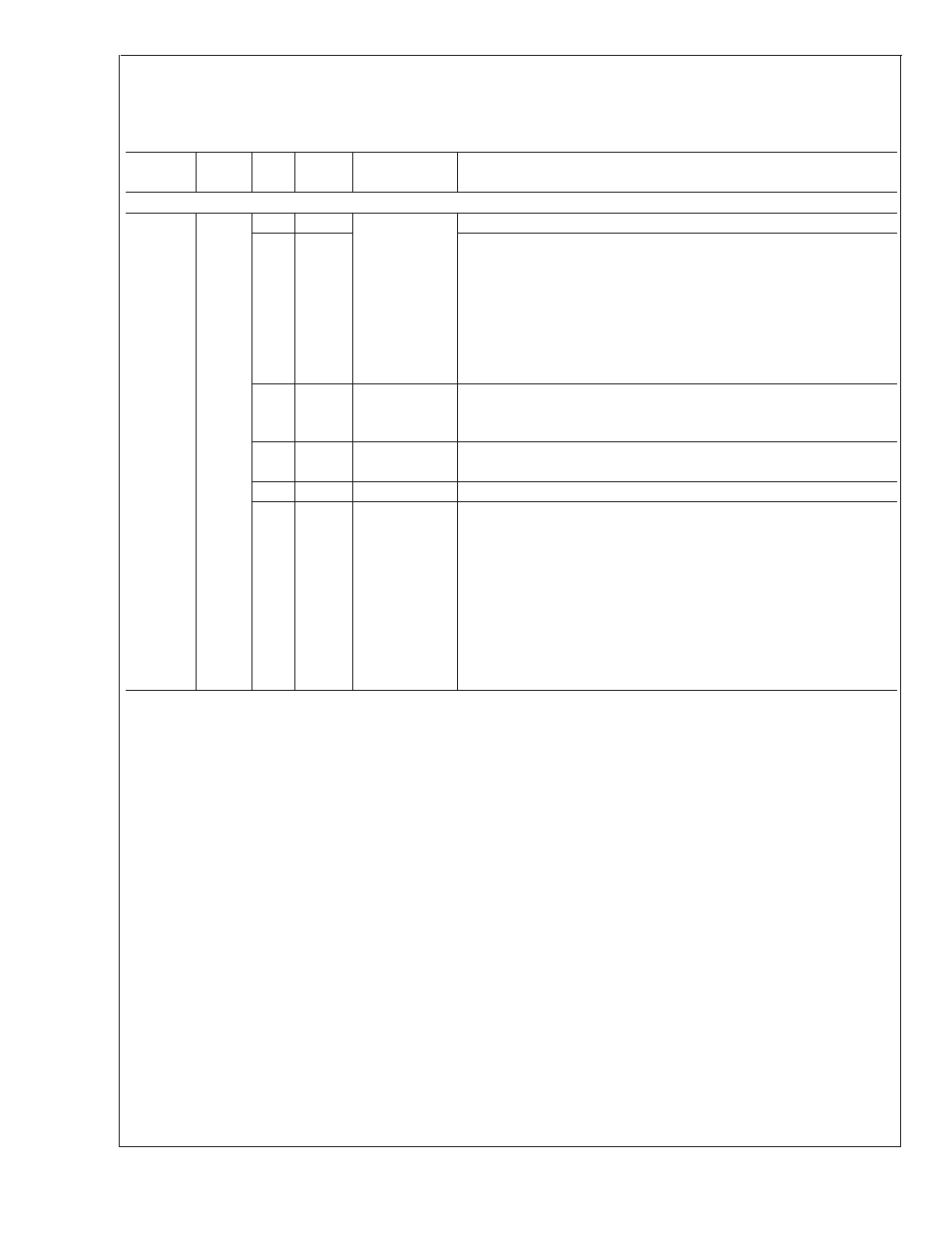
2.0 LM63 Registers
(Continued)
LM63 Register Descriptions In Functional Order
Fan Control Registers
Address
Hex
Read/
Write
Bits
POR
Value
Name
Description
4A
HEX
FAN PWM AND TACHOMETER CONFIGURATION REGISTER
4A
R/W
7:6
00
PWM
Program
These bits are unused and always set to 0.
5
1
0: the PWM Value (register 4C) and the Lookup Table (50–5F) are
read-only. The PWM value (0 to 100%) is determined by the current
remote diode temperature and the Lookup Table, and can be read from
the PWM value register.
1: the PWM value (register 4C) and the Lookup Table (Register 50–5F)
are read/write enabled. Writing the PWM Value register will set the
PWM output. This is also the state during which the Lookup Table can
be written.
4
0
PWM
Output
Polarity
0: the PWM output pin will be 0 V for fan OFF and open for fan ON.
1: the PWM output pin will be open for fan OFF and 0 V for fan ON.
3
0
PWM Clock
Select
if 0, the master PWM clock is 360 kHz
if 1, the master PWM clock is 1.4 kHz.
2
0
[Reserved]
Always write 0 to this bit.
1:0
00
Tachometer
Mode
00: Traditional tach input monitor, false readings when under minimum
detectable RPM.
01: Traditional tach input monitor, FFFF reading when under minimum
detectable RPM.
10: Most accurate readings, FFFF reading when under minimum
detectable RPM.
11: Least effort on programmed PWM of fan, FFFF reading when under
minimum detectable RPM.
Note: If the PWM Clock is 360 kHz, mode 00 is used regardless of the
setting of these two bits.
LM63
www.national.com
16