Pin descriptions, Simplified block diagram – Rainbow Electronics LM63 User Manual
Page 2
Pin Descriptions
Pin
Name
Input/Output
Function and Connection
1
V
DD
Power Supply Input
Connect to a low-noise +3.3
±
0.3 VDC power supply, and bypass to GND
with a 0.1 µF ceramic capacitor in parallel with a 100 pF ceramic capacitor.
A bulk capacitance of 10 µF needs to be in the vicinity of the LM63’s V
DD
pin.
2
D+
Analog Input
Connect to the anode (positive side) of the remote diode. A 2.2 nF ceramic
capacitor must be connected between pins 2 and 3.
3
D−
Analog Input
Connect to the cathode (negative side) of the remote diode. A 2.2 nF
ceramic capacitor must be connected between pins 2 and 3.
4
PWM
Open-Drain
Digital Output
Open-Drain Digital Output. Connect to fan drive circuitry. The power-on
default for this pin is low (pin 4 pulled to ground).
5
GND
Ground
This is the analog and digital ground return.
6
ALERT/TACH
Digital I/O
Depending on how the LM63 is programmed, this pin is either an
open-drain ALERT output or a tachometer input for measuring fan speed.
The power-on default for this pin is the ALERT function.
7
SMBDAT
Digital Input/
Open-Drain Output
This is the bi-directional SMBus data line.
8
SMBCLK
Digital Input
Digital Input. This is the SMBus clock input.
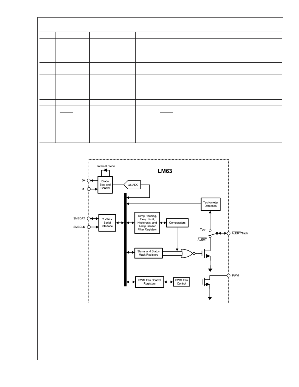
Simplified Block Diagram
20057002
LM63
www.national.com
2