Electrical characteristics (continued) – Rainbow Electronics MAX1545 User Manual
Page 3
MAX1519/MAX1545
Dual-Phase, Quick-PWM Controllers for
Programmable CPU Core Power Supplies
_______________________________________________________________________________________
3
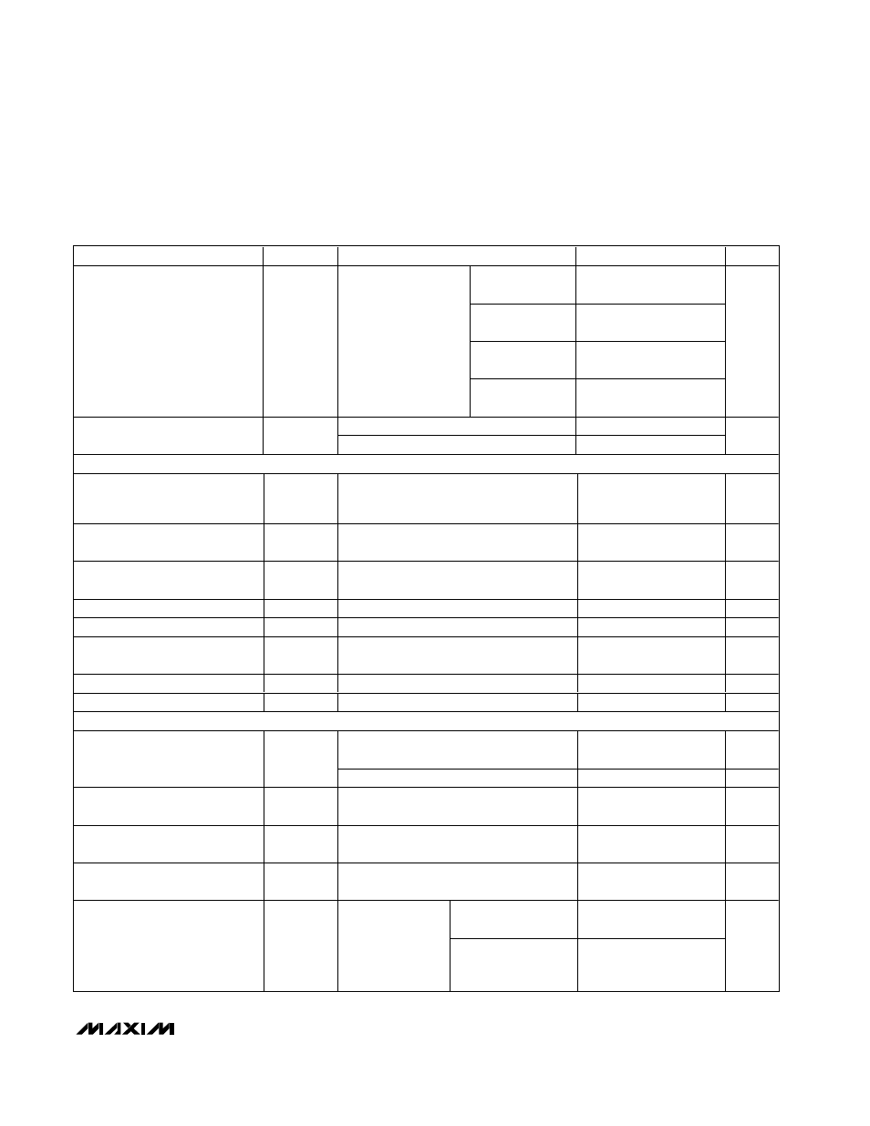
ELECTRICAL CHARACTERISTICS (continued)
(Circuit of Figure 1, V+ = 15V, V
CC
= V
DD
= V
SHDN
= V
TON
= V
SKIP
= V
S0
= V
S1
= V
CODE
= 5V, V
FB
= V
CMP
= V
CMN
= V
CSP
= V
CSN
= 1.3V, OFS = SUS = GNDS = D0–D4 = GND; T
A
= 0°C to +85°C, unless otherwise specified. Typical values are at T
A
= +25°C.)
PARAMETER
SYMBOL
CONDITIONS
MIN
TYP
MAX
UNITS
TON = GND
(550kHz)
155
180
205
TON = REF
(300kHz)
320
355
390
TON = open
(200kHz)
475
525
575
On-Time (Note 3)
t
ON
V+ = 12V,
V
FB
= V
CCI
= 1.2V
TON = V
CC
(100kHz)
920
1000
1140
ns
TON = GND
300
375
Minimum Off-Time (Note 3)
t
OFF(MIN)
TON = V
CC
, open, or REF
400
480
ns
BIAS AND REFERENCE
Quiescent Supply Current (V
CC
)
I
CC
Measured at V
CC
, FB forced above the
regulation point, OAIN- = FB,
V
OAIN+
= 1.3V
1.70
3.20
mA
Quiescent Supply Current (V
DD
)
I
DD
Measured at V
DD
, FB forced above the
regulation point
<1
5
µA
Quiescent Battery Supply Current
(V+)
I
V+
Measured at V+
25
40
µA
Shutdown Supply Current (V
CC
)
Measured at V
CC
,
SHDN = GND
4
10
µA
Shutdown Supply Current (V
DD
)
Measured at V
DD
,
SHDN = GND
<1
5
µA
Shutdown Battery Supply Current
(V+)
Measured at V+,
SHDN = GND,
V
CC
= V
DD
= 0 or 5V
<1
5
µA
Reference Voltage
V
REF
V
CC
= 4.5V to 5.5V, I
REF
= 0
1.990
2.000
2.010
V
Reference Load Regulation
∆V
REF
I
REF
= -10µA to +100µA
-10
+10
mV
FAULT PROTECTION
SKIP = V
CC
, measured at FB with respect
to unloaded output voltage
13
16
19
%
Output Overvoltage Protection
Threshold (MAX1545 Only)
V
OVP
SKIP = REF or GND
2.00
V
Output Overvoltage Propagation
Delay (MAX1545 Only)
t
OVP
FB forced 2% above trip threshold
10
µs
Output Undervoltage Protection
Threshold
V
UVP
Measured at FB with respect to unloaded
output voltage
67
70
73
%
Output Undervoltage Propagation
Delay
t
UVP
FB forced 2% below trip threshold
10
µs
Lower threshold
(undervoltage)
-12
-10
-8
VROK Threshold
Measured at FB
with respect to
unloaded output
voltage
Upper threshold
(overvoltage)
SKIP = V
CC
+8
+10
+12
%