Table 3. operating mode truth table – Rainbow Electronics MAX1545 User Manual
Page 20
MAX1519/MAX1545
Dual-Phase, Quick-PWM Controllers for
Programmable CPU Core Power Supplies
20
______________________________________________________________________________________
When SHDN goes high, the reference powers up. Once
the reference voltage exceeds its UVLO threshold, the
controller evaluates the DAC target and starts switching.
The slew-rate controller ramps up from 0V in 25mV
increments to the currently selected output-voltage set-
ting (see the Power-Up Sequence section). There is no
traditional soft-start (variable current-limit) circuitry, so
full output current is available immediately.
Internal Multiplexers
The MAX1519/MAX1545 have a unique internal DAC
input multiplexer (muxes) that selects one of three differ-
ent DAC code settings for different processor states
(Figure 3). On startup, the MAX1519/MAX1545 select the
DAC code from the D0–D4 (SUS = GND) or S0–S1 (SUS
= REF or high) input decoders.
DAC Inputs (CODE, D0–D4)
During normal forced-PWM operation (SUS = GND), the
DAC programs the output voltage using code and the
D0–D4 inputs. Connect CODE to V
CC
or GND for the
mobile or desktop P4 setting, respectively. Do not leave
D0–D4 unconnected. D0–D4 can be changed while the
MAX1519/MAX1545 are active, initiating a transition to
a new output voltage level. Change D0–D4 together,
avoiding greater than 1µs skew between bits.
Otherwise, incorrect DAC readings can cause a partial
transition to the wrong voltage level followed by the
intended transition to the correct voltage level, length-
ening the overall transition time. The available DAC
codes and resulting output voltages are compatible
with desktop and mobile P4 (Table 4) specifications.
Four-Level Logic Inputs
TON and S0–S1 are four-level logic inputs. These
inputs help expand the functionality of the controller
without adding an excessive number of pins. The four-
level inputs are intended to be static inputs. When left
open, an internal resistive voltage-divider sets the input
voltage to approximately 3.5V. Therefore, connect the
four-level logic inputs directly to V
CC
, REF, or GND
when selecting one of the other logic levels. See
Electrical Characteristics for exact logic level voltages.
Suspend Mode
When the processor enters low-power suspend mode, it
sets the regulator to a lower output voltage to reduce
power consumption. The MAX1519/MAX1545 include
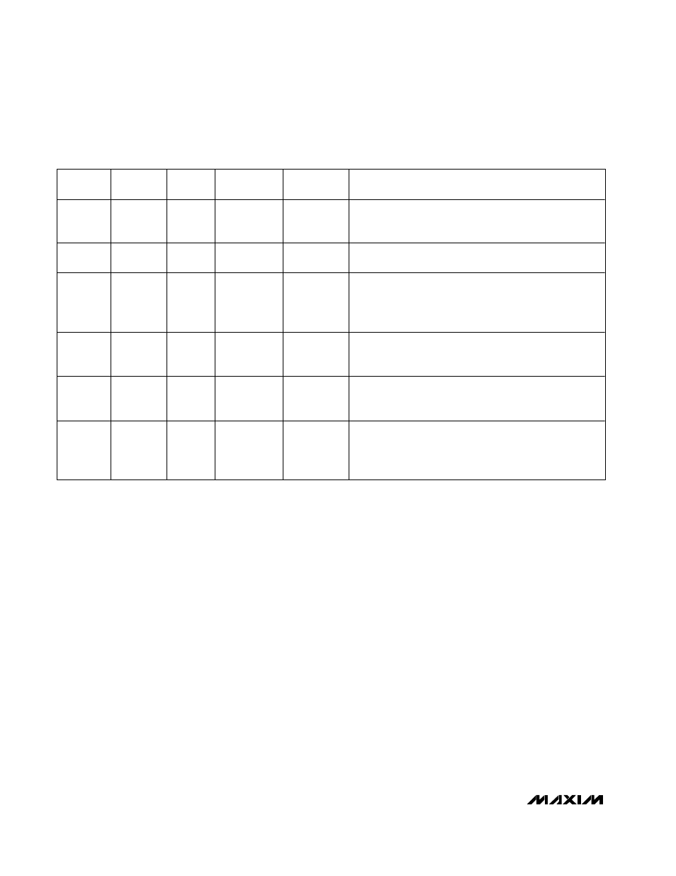
SHDN
SUS
SKIP
OFS
OUTPUT
VOLTAGE
OPERATING MODE
GND
x
x
x
GND
Low-Power Shutdown Mode. DL_ is forced high, DH_ is
forced low, and the PWM controller is disabled. The supply
current drops to 1µA (typ).
V
CC
GND
V
CC
GND or REF
D0–D4
(no offset)
N or m al Op er ati on. The no- l oad outp ut vol tag e i s d eter m i ned b y
the sel ected V ID D AC cod e ( C OD E and D 0–D 4, Tab l e 4) .
V
CC
x
REF
or
GND
GND or REF
D0–D4
(no offset)
Pulse-Skipping Operation. When
SKIP is pulled low, the
MAX1519/MAX1545 immediately enter pulse-skipping
operation, allowing automatic PWM/PFM switchover under
light loads. The VROK upper threshold is blanked.
V
CC
GND
x
0 to 0.8V
or
1.2V to 2V
D0–D4
(plus offset)
Deep-Sleep Mode. The no-load output voltage is determined
by the selected VID DAC cod e ( C OD E and D 0–D 4, Table 4),
plus the offset voltage set by OFS.
V
CC
REF
or
high
x
x
SUS, S0–S1
(no offset)
Suspend Mode. The no-load output voltage is determined by
the selected suspend code (SUS, S0–S1, Table 5),
overriding all other active modes of operation.
V
CC
x
x
x
GND
Fault Mode. The fault latch has been set by either UVP, OVP
(MAX1545 only), or thermal shutdown. The controller
remains in FAULT mode until V
CC
power is cycled or
SHDN
toggled.
Table 3. Operating Mode Truth Table