Rainbow Electronics MAX1545 User Manual
Page 21
MAX1519/MAX1545
Dual-Phase, Quick-PWM Controllers for
Programmable CPU Core Power Supplies
______________________________________________________________________________________
21
independent suspend-mode output voltage codes set by
the four-level S0–S1 inputs and the three-level SUS input.
When the CPU suspends operation (SUS = REF or high),
the controller disables the offset amplifier and overrides
the 5-bit VID DAC code set by D0–D4 (normal operation).
The master controller slews the output to the selected
suspend-mode voltage. During the transition, the
MAX1519/MAX1545 blank VROK and the UVP fault pro-
tection until 24 R
TIME
clock cycles after the slew-rate con-
troller reaches the suspend-mode voltage.
SUS is a three-level logic input: GND, REF, or high. This
expands the functionality of the controller without
adding an additional pin. This input is intended to be
driven by a dedicated open-drain output with the pullup
resistor connected either to REF (or a resistive-divider
from V
CC
) or to a logic-level bias supply (3.3V or
greater). When pulled up to REF, the MAX1519/
MAX1545 select the upper suspend voltage range.
When pulled high (2.7V or greater), the controller
selects the lower suspend voltage range. See Electrical
Characteristics for exact logic level voltages.
Output Voltage Transition Timing
The MAX1519/MAX1545 are designed to perform mode
transitions in a controlled manner, automatically minimiz-
ing input surge currents. This feature allows the circuit
designer to achieve nearly ideal transitions, guaranteeing
just-in-time arrival at the new output voltage level with the
lowest possible peak currents for a given output capaci-
tance.
At the beginning of an output voltage transition, the
MAX1519/MAX1545 blank the VROK output, preventing
them from changing states. VROK remains blanked dur-
ing the transition and is enabled 24 clock cycles after the
slew-rate controller has set the final DAC code value.
The slew-rate clock frequency (set by resistor R
TIME
)
must be set fast enough to ensure that the transition is
completed within the maximum allotted time.
The slew-rate controller transitions the output voltage in
25mV steps during soft-start, soft-shutdown, and sus-
pend-mode transitions. The total time for a transition
depends on R
TIME
, the voltage difference, and the
accuracy of the MAX1519/MAX1545s’ slew-rate clock,
and is not dependent on the total output capacitance.
The greater the output capacitance, the higher the
surge current required for the transition. The
MAX1519/MAX1545 automatically control the current to
the minimum level required to complete the transition in
the calculated time, as long as the surge current is less
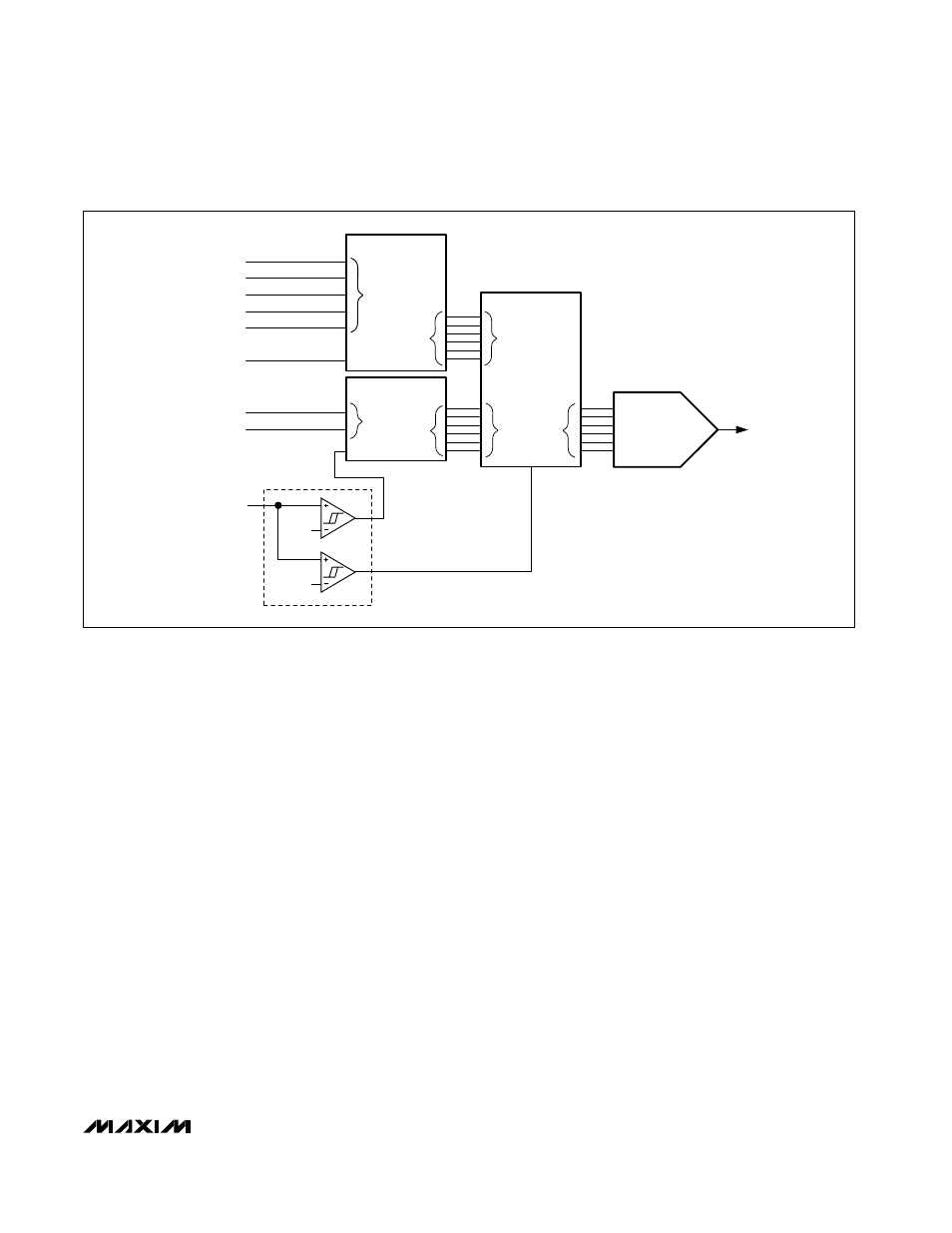
Figure 3. Internal Multiplexers Functional Diagram
D0
D1
D2
D3
D4
CODE
S0
S1
SUSPEND
MUX
0
SEL
DAC
1
D0–D4
DECODER
OUT
IN
SEL
SEL
OUT
S0–S1
DECODER
IN
OUT
SUS
1.0V
2.5V
SUS 3-LEVEL
DECODER