Applications information, Table 1. control logic, Table 2. operating modes – Rainbow Electronics MAX2062 User Manual
Page 18
18 _____________________________________________________________________________________
MAX2062
Dual 50MHz to 1000MHz High-Linearity,
Serial/Parallel-Controlled Analog/Digital VGA
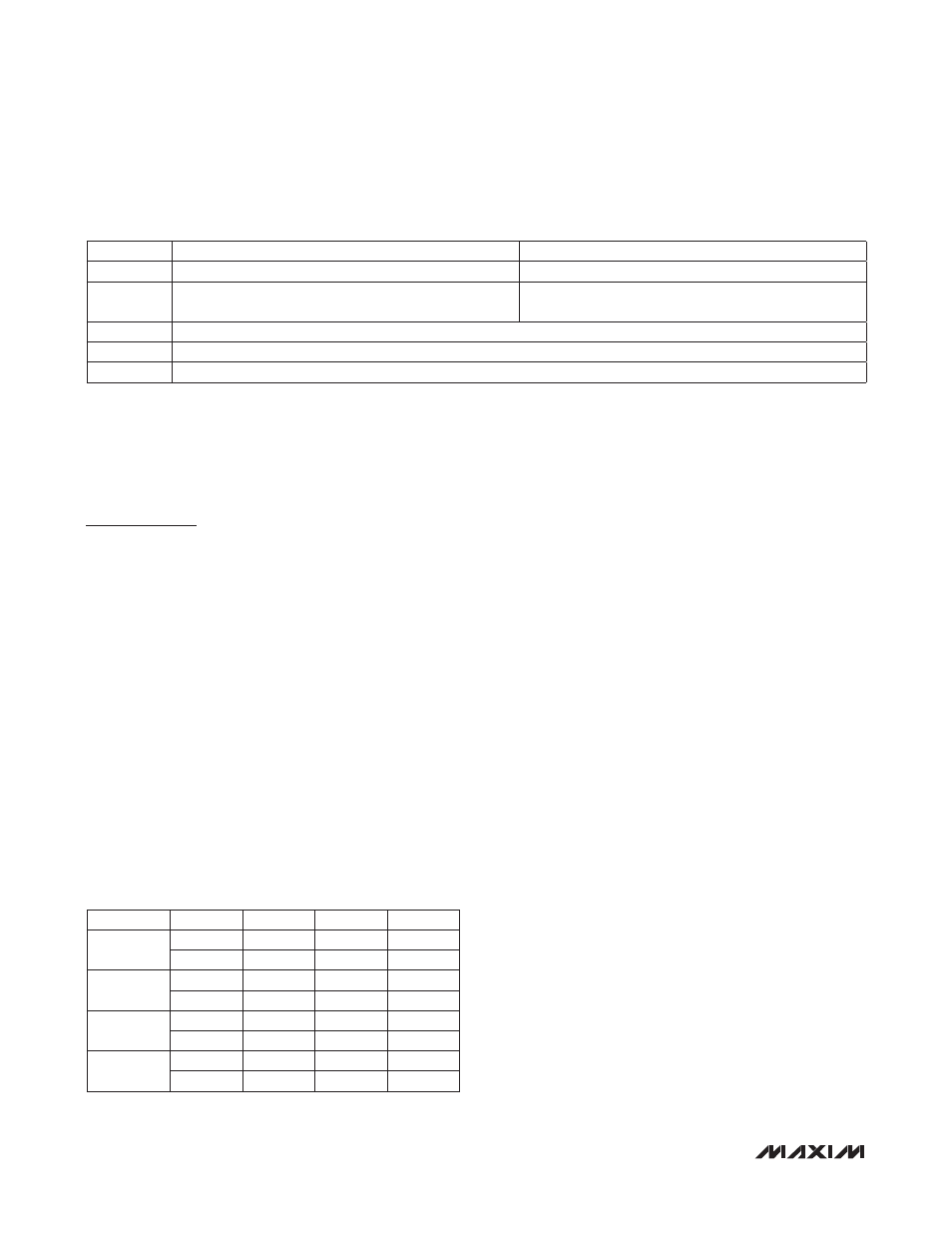
Table 1. Control Logic
Driver Amplifier
Each path of the device includes a high-performance
driver with a fixed gain of 24dB. The driver amplifier
circuits are optimized for high linearity for the 50MHz to
1000MHz frequency range.
Applications Information
Operating Modes
The device features an optional +3.3V supply volt-
age operation with reduced linearity performance. The
AMPSET pin needs to be biased accordingly in each
mode, as listed in Table 2. In addition, the driver amplifiers
can be shut down independently to conserve DC power.
See the biasing scheme outlined in Table 2 for details.
SPI Interface and Attenuator Settings
The digital attenuators can be programmed through the
3-wire SPI/MICROWIREK-compatible serial interface
using 5-bit words. Fifty-six bits of data are shifted in
MSB first and are framed by CS. The first 28 bits set the
first attenuator and the following 28 bits set the second
attenuator. When CS is low, the clock is active and data
is shifted on the rising edge of the clock. When CS transi-
tions high, the data is latched and the attenuator setting
changes (Figure 1). See Table 3 for details on the SPI
data format.
Path 1 DAC and Digital Attenuator Programming
D0:D7
Sent to DAC register
D0 = LSB, D7 = MSB
D8:D12
Preprogrammed Attenuation State 1
D8 = 1dB bit, D9 = 2dB Bit, D10 = 4dB bit,
D11 = 8dB bit, D12 = 16dB bit
D13:D17
Preprogrammed Attenuation State 2
D13 = 1dB bit, D14 = 2dB bit, D15 = 4dB
bit, D16 = 8dB bit, D17 = 16dB bit
D18:D22
Preprogrammed Attenuation State 3
D18 = 1dB bit, D19 = 2dB bit, D20 = 4dB
bit, D21 = 8dB bit, D22 = 16dB bit
D23:D27
Preprogrammed Attenuation State 4
D23 = 1dB bit, D24 = 2dB bit, D25 = 4dB
bit, D26 = 8dB bit, D27 = 16dB bit
Path 2 DAC and Digital Attenuator Programming
D28:D35 Sent to DAC register
D28 = LSB, D35 = MSB
D36:D40
Preprogrammed Attenuation State 1
D36 = 1dB bit, D37 = 2dB bit, D38 = 4dB
bit, D39 = 8dB bit, D40 = 16dB bit
D41:D45
Preprogrammed Attenuation State 2
D41 = 1dB bit, D42 = 2dB bit, D43 = 4dB
bit, D44 = 8dB bit, D45 = 16dB bit
D46:D50
Preprogrammed Attenuation State 3
D46 = 1dB bit, D47 = 2dB bit, D48 = 4dB
bit, D49 = 8dB bit, D50 = 16dB bit
D51:D55
Preprogrammed Attenuation State 4
D51 = 1dB bit, D52 = 2dB bit, D53 = 4dB
bit, D54 = 8dB bit, D55 = 16dB bit
Table 2. Operating Modes
MICROWIRE is a trademark of National Semiconductor Corp.
AA_SP
ANALOG ATTENUATOR
D/A CONVERTER
0
Controlled by external control voltage
Disabled
1
Controlled by on-chip DAC
Enabled (DAC output voltage shows on A_VCTL__ pins);
DAC uses on-chip voltage reference
DA_SP
DIGITAL ATTENUATOR
0
Parallel controlled
1
SPI controlled (control voltages show up on the parallel control pins)
RESULT
V
CC
(V)
AMPSET
PD_1
PD_2
All on
5
0
0
0
3.3
1
0
0
AMP1 off
AMP2 on
5
0
1
0
3.3
1
1
0
AMP1 on
AMP2 off
5
0
0
1
3.3
1
0
1
All off
5
0
1
1
3.3
1
1
1