Pin configuration pin description – Rainbow Electronics MAX2062 User Manual
Page 15
______________________________________________________________________________________ 15
MAX2062
Dual 50MHz to 1000MHz High-Linearity,
Serial/Parallel-Controlled Analog/Digital VGA
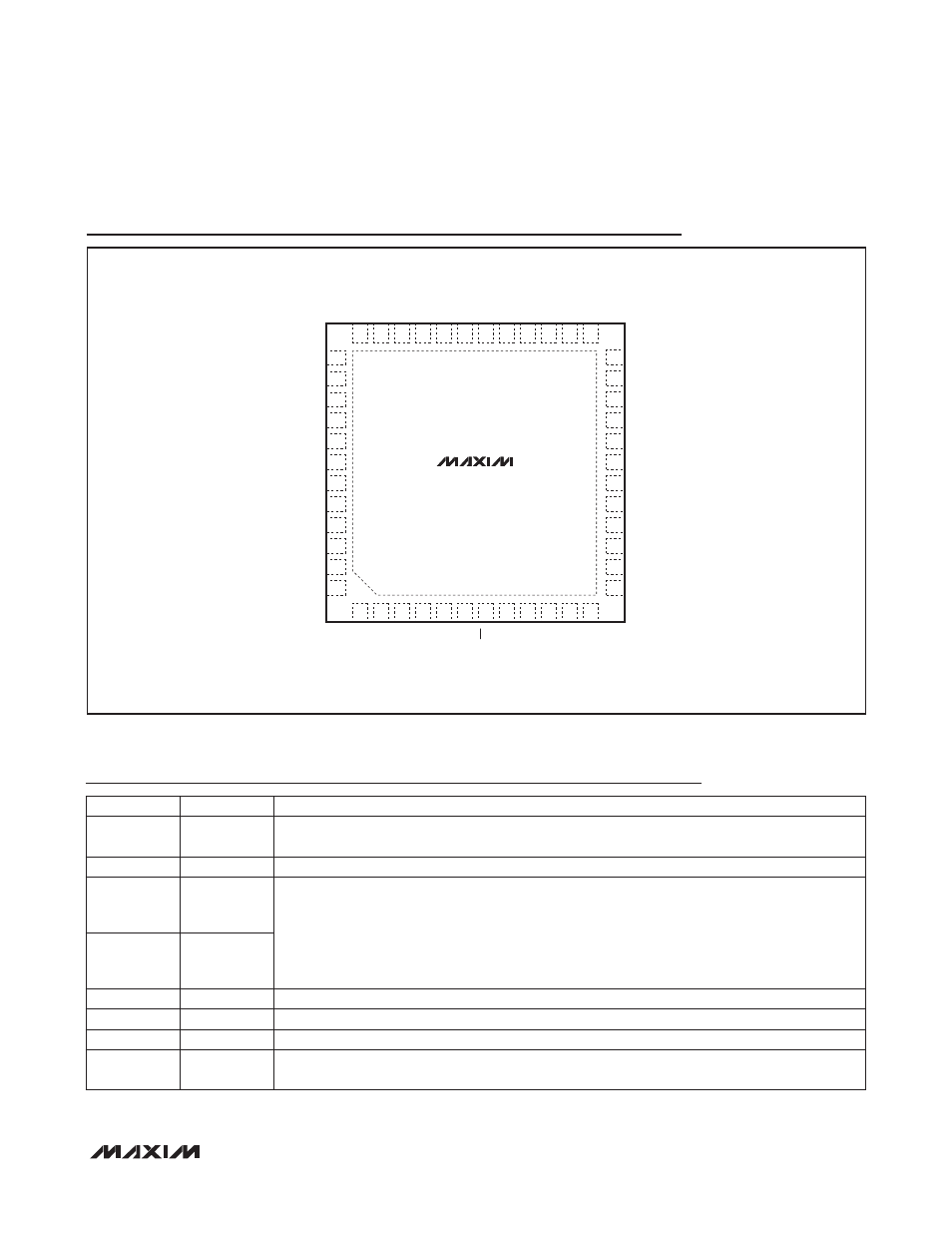
Pin Configuration
Pin Description
TOP VIEW
MAX2062
TQFN
+
13
14
15
16
17
18
19
20
21
22
23
24
GND
D0_2
D1_2
D2_2
D3_2
D_ATT_OUT_2
D4_2
A_ATT_IN_2
DA_SP
A_VCTL_2
A_ATT_OUT_2
V
CC_AMP_2
48
47
46
45
44
43
42
41
40
39
38
37
1
2
3
4
5
6
7
8
9
10 11 12
EP
GND
D0_1
D1_1
D2_1
D3_1
D_ATT_OUT_1
D4_1
A_ATT_IN_1
AA_SP
A_VCTL_1
A_ATT_OUT_1
V
CC_AMP_1
GND
D_ATT_IN_2
STA_A_2
STA_B_2
V
CC_RG
CLK
DAT
STA_B_1
STA_A_1
D_ATT_IN_1
GND
36 35 34 33 32 31 30 29 28 27 26 25
GND
AMP_IN_2
PD_2
GND
AMP_OUT_2
REG_OUT
AMPSET
AMP_OUT_1
GND
PD_1
AMP_IN_1
GND
CS
PIN
NAME
FUNCTION
1, 12, 13, 25,
28, 33, 36, 48
GND
Ground
2
D_ATT_IN_1 5-Bit Digital Attenuator Input (50I), Path 1. Requires a DC-blocking capacitor.
3
STA_A_1
Digital Attenuator Preprogrammed Attenuation-State Logic Input, Path 1
State A
State B
Digital Attenuator
Logic = 0
Logic = 0
Preprogrammed State 1
Logic = 1
Logic = 0
Preprogrammed State 2
Logic = 0
Logic = 1
Preprogrammed State 3
Logic = 1
Logic = 1
Preprogrammed State 4
4
STA_B_1
5
DAT
SPI Data Digital Input
6
CLK
SPI Clock Digital Input
7
CS
SPI Chip-Select Digital Input
8
V
CC_RG
Regulator Supply Input. Connect to a 3.3V or 5V external power supply. V
CC_RG
powers all circuits
except for the driver amplifiers. Bypass with a 10nF capacitor as close as possible to the pin.