Pin description (continued) – Rainbow Electronics MAX2062 User Manual
Page 16
16 _____________________________________________________________________________________
MAX2062
Dual 50MHz to 1000MHz High-Linearity,
Serial/Parallel-Controlled Analog/Digital VGA
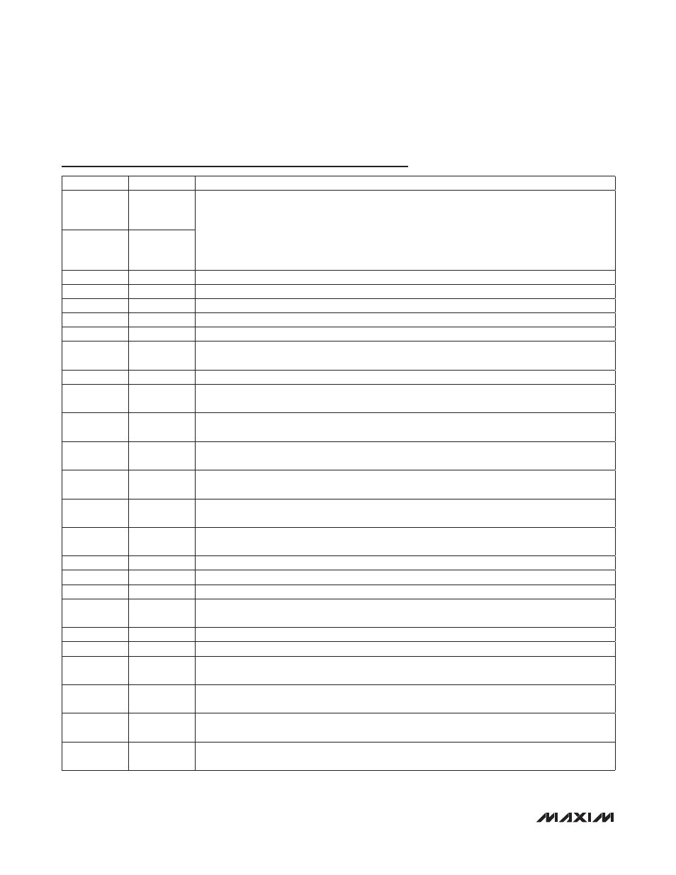
Pin Description (continued)
PIN
NAME
FUNCTION
9
STA_B_2
Digital Attenuator Preprogrammed Attenuation-State Logic Input, Path 2
State A
State B
Digital Attenuator
Logic = 0
Logic = 0
Preprogrammed State 1
Logic = 1
Logic = 0
Preprogrammed State 2
Logic = 0
Logic = 1
Preprogrammed State 3
Logic = 1
Logic = 1
Preprogrammed State 4
10
STA_A_2
11
D_ATT_IN_2 5-Bit Digital Attenuator Input (50I), Path 2. Requires a DC-blocking capacitor.
14
D0_2
1dB Attenuator Logic Input, Path 2. Logic 0 = disable, logic 1 = enable.
15
D1_2
2dB Attenuator Logic Input, Path 2. Logic 0 = disable, logic 1 = enable.
16
D2_2
4dB Attenuator Logic Input, Path 2. Logic 0 = disable, logic 1 = enable.
17
D3_2
8dB Attenuator Logic Input, Path 2. Logic 0 = disable, logic 1 = enable.
18
D_ATT_OUT_2
5-Bit Digital Attenuator Output (50I), Path 2. Requires a DC-blocking capacitor. Connect to
A_ATT_IN_2 through a 1000pF capacitor.
19
D4_2
16dB Attenuator Logic Input, Path 2. Logic 0 = disable, logic 1 = enable.
20
A_ATT_IN_2
Analog Attenuator Input (50I), Path 2. Requires a DC-blocking capacitor. Connect to
D_ATT_OUT_2 through a 1000pF capacitor.
21
DA_SP
Digital Attenuator Serial/Parallel Control Select. Set DA_SP to logic 1 to select serial control.
Set DA_SP to logic 0 to select parallel control.
22
A_VCTL_2
Analog Attenuator Voltage Control Input, Path 2. Bypass to ground with a 150pF capacitor
if on-chip DAC is used (AA_SP = 1).
23
A_ATT_OUT_2
Analog Attenuator Output (50I), Path 2. Requires a DC-blocking capacitor. Connect to
AMP_IN_2 through a 1000pF capacitor.
24
V
CC_AMP_2
Driver Amplifier Supply Voltage Input, Path 2. Bypass with a 10nF capacitor as close as
possible to the pin.
26
AMP_IN_2
Driver Amplifier Input (50I), Path 2. Requires a DC-blocking capacitor. Connect to
A_ATT_OUT_2 through a 1000pF capacitor.
27
PD_2
Power-Down, Path 2. See Table 2 for operation details.
29
AMP_OUT_2 Driver Amplifier Output (50I), Path 2. Connect a pullup inductor from AMP_OUT_2 to V
CC_.
30
REG_OUT
Regulator Output. Bypass with 1FF capacitor.
31
AMPSET
Driver Amplifier Bias Setting for 3.3V Operation. Set to logic 1 for 3.3V operation on pins
V
CC_AMP_1
and V
CC_AMP_2
. Set to logic 0 for 5V operation.
32
AMP_OUT_1 Driver Amplifier Output (50I), Path 1. Connect a pullup inductor from AMP_OUT_1 to V
CC_.
34
PD_1
Power-Down, Path 1. See Table 2 for operation details.
35
AMP_IN_1
Driver Amplifier Input (50I), Path 1. Requires a DC-blocking capacitor. Connect to
A_ATT_OUT_1 through a 1000pF capacitor.
37
V
CC_AMP_1
Driver Amplifier Supply Voltage Input, Path 1. Bypass with a 10nF capacitor as close as
possible to the pin.
38
A_ATT_OUT_1
Analog Attenuator Output (50I), Path 1. Requires a DC-blocking capacitor. Connect to
AMP_IN_1 through a 1000pF capacitor.
39
A_VCTL_1
Analog Attenuator Voltage Control Input, Path 1. Bypass to ground with a 150pF capacitor
if on-chip DAC is used (AA_SP = 1).