Table 2. serial-interface programming commands – Rainbow Electronics MAX513 User Manual
Page 11
MAX512/MAX513
Low-Cost, Triple, 8-Bit Voltage-Output DACs
with Serial Interface
______________________________________________________________________________________
11
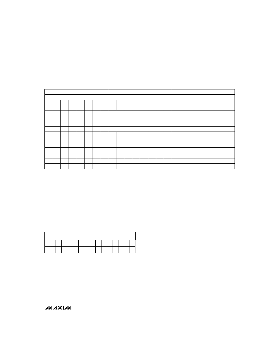
Serial-Input Data Format and Control Codes
Table 2 lists the serial-input data format. The 16-bit
input word consists of an 8-bit control byte and an 8-bit
data byte. The 8-bit control byte is not decoded inter-
nally. Every control bit performs one function. Data is
clocked in starting with Q2 (uncommitted bit), followed
by the remaining control bits and the data byte. The
LSB of the data byte (B0) is the last bit clocked into the
shift register (Figure 2).
Example of a 16-bit input word:
The example above performs the following functions:
• 80hex (128 decimal) loaded into DAC registers
A and B.
• Content of the DAC C register remains unchanged.
• DAC A and DAC B are active.
• DAC C is shut down.
• LOUT is reset to 0.
Digital Inputs
The digital inputs are compatible with CMOS logic.
Supply current increases slightly when toggling the
logic inputs through the transition zone between
(0.3)(V
DD
) and (0.7)(V
DD
).
Digital Output
The latched digital output (LOUT) has a 1.6mA source
capability while maintaining a (V
DD
- 0.4V) output level.
With a 1.6mA sink current, the output voltage is guaran-
teed to be no more than 0.4V. The output can be used
for digital auxiliary control. Please note that the digital
output remains fully active during shutdown mode.
Microprocessor Interfacing
The MAX512/MAX513 serial interface is compatible with
Microwire, SPI, and QSPI. For SPI and QSPI, clear the
CPOL and CPHA bits (CPOL = 0 and CPHA = 0).
CPOL = 0 sets the inactive state of clock to zero and
CPHA = 0 changes data at the falling edge of SCLK.
This setting allows both SPI and QSPI to run at full clock
speeds (0.5MHz and 4MHz, respectively). If a serial port
is not available on your µP, three bits of a parallel port
can be used to emulate a serial port by bit manipulation.
Minimize digital feedthrough at the voltage outputs by
operating the serial clock only when necessary.
CONTROL
DATA
Q2
Q1
SC
SB
SA
LC
LB
LA
B7
B4
B3
B2
B1
B0
FUNCTION
*
*
*
*
*
0
0
0
X
X
X
X
X
X
X
X
No Operation to DAC Registers
*
8-Bit DAC Data
Load Register to DAC C
*
8-Bit DAC Data
Load Register to DAC B
*
8-Bit DAC Data
Load Register to DAC A
*
8-Bit DAC Data
Load All DAC Registers
*
*
0
0
0
*
*
*
X
X
X
X
X
X
X
X
All DACs Active
*
*
1
0
0
*
*
*
X
X
X
X
X
X
X
X
Shut Down DAC C
*
*
0
1
0
*
*
*
X
X
X
X
X
X
X
X
Shut Down DAC B
*
*
0
0
1
*
*
*
X
X
X
X
X
X
X
X
Shut Down DAC A
*
*
1
1
1
*
*
*
X
X
X
X
X
X
X
X
Shut Down All DACs
X
0
*
*
*
*
*
*
X
X
X
X
X
X
X
X
Reset LOUT
X
1
*
*
*
*
*
*
X
X
X
X
X
X
X
X
Set LOUT
B5
B6
Table 2. Serial-Interface Programming Commands
X
Don’t care.
*
Not shown for clarity. The functions of loading and shutting down the DACs and programming the logic can be combined in a single command.
MSB
LSB
1
0
0
1
0
1
1
0
*
0
*
*
*
*
*
*
*
*
0
*
1
*
*
1
*
*
*
*
X
0
1
0
0
0
1
1
1
0
0
0
0
0
0
0
Q2 Q1 SC SB SA LC LB LA B7 B6 B5 B4 B3 B2 B1 B0
Loaded
Loaded
in First
in Last