Max108 – Rainbow Electronics MAX108 User Manual
Page 24
MAX108
current with an ammeter (which shuts off the internal
catch diodes) referenced to GNDI. The die temperature
in °C is then calculated by the expression:
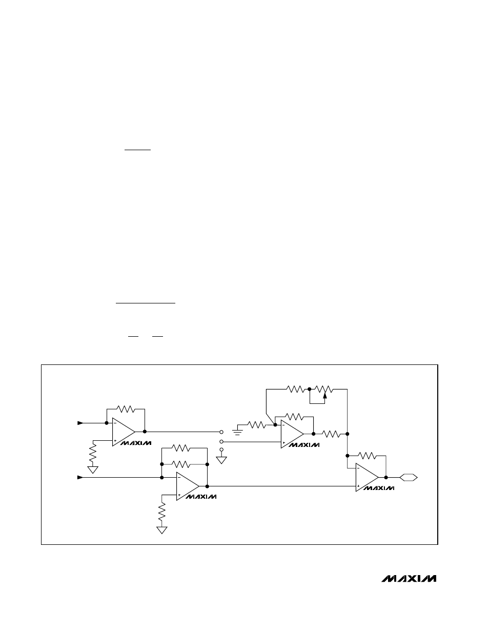
Another method of determining the die temperature
uses the operational amplifier circuit shown in Figure
20. The circuit produces a voltage that is proportional
to the die temperature. A possible application for this
signal is speed control for a cooling fan to maintain
constant MAX108 die temperature. The circuit operates
by converting the I
CONST
and I
PTAT
currents to volt-
ages V
CONST
and V
PTAT
, with appropriate scaling to
account for their equal values at +27°C. This voltage
difference is then amplified by two amplifiers in an
instrumentation-amplifier configuration with adjustable
gain. The nominal value of the circuit gain is 4.5092V/V.
The gain of the instrumentation amplifier is given by the
expression:
To calibrate the circuit, first connect pins 2 and 3 on
JU1 to zero the input of the PTAT path. With the
MAX108 powered up, adjust potentiometer R3 until the
voltage at the V
TEMP
output is -2.728V. Connecting
pins 1 and 2 on JU1 restores normal operation to the
circuit after the calibration is complete. The voltage at
the V
TEMP
node will then be proportional to the actual
MAX108 die temperature according to the equation:
T
DIE
(°C) = 100 V
TEMP
The overall accuracy of the die temperature measure-
ment using the operational-amplifier scaling circuitry is
limited mainly by the accuracy and matching of the
resistors in the circuit.
Thermal Management
Depending on the application environment for the
ESBGA-packaged MAX108, the customer may have to
apply an external heatsink to the package after board
assembly. Existing open-tooled heatsinks are available
from standard heatsink suppliers (see
Heatsink
Manufacturers
). The heatsinks are available with preap-
plied adhesive for easy package mounting.
A
V
V
V
A
R
R
R
R
V
TEMP
CONST
PTAT
V
=
−
= +
+
1
1
2
2
1
3
T
I
I
DIE
PTAT
CONST
=
−
300
273
±5V, 1.5Gsps, 8-Bit ADC with
On-Chip 2.2GHz Track/Hold Amplifier
24
______________________________________________________________________________________
Figure 20. Die Temperature Acquisition Circuit with the MAX479
V
CONST
V
TEMP
R1
7.5k
R2
15k
R2
15k
3.32k
5k
R1
7.5k
6.65k
6.65k
6.05k
12.1k
12.1k
1
2
3
JU1
10-TURN
I
PTAT
V
PTAT
I
CONST
1/4 MAX479
1/4 MAX479
1/4 MAX479
1/4 MAX479