Pin description (continued) – Rainbow Electronics MAX108 User Manual
Page 11
MAX108
±5V, 1.5Gsps, 8-Bit ADC with
On-Chip 2.2GHz Track/Hold Amplifier
______________________________________________________________________________________
11
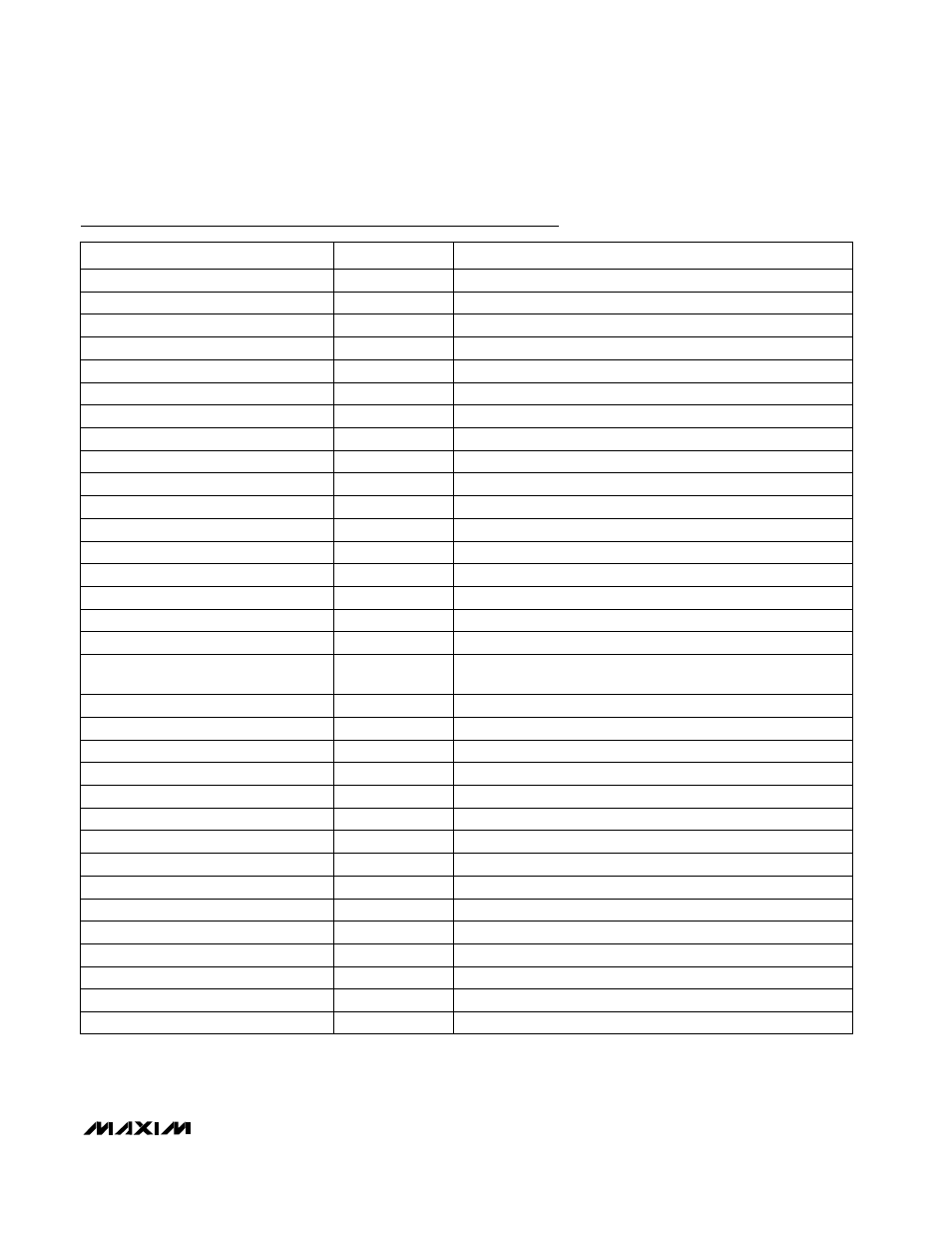
Pin Description (continued)
K18
DREADY+
Data-Ready Clock
L1
VIN+
Differential Input Voltage (+)
K17
DREADY-
Complementary Data-Ready Clock
V13
A7+
Auxiliary Output Data Bit 7 (MSB)
V15
A6+
Auxiliary Output Data Bit 6
V16
P6+
Primary Output Data Bit 6
V14
P7+
Primary Output Data Bit 7 (MSB)
V12
OR+
PECL Overrange Bit
V10
RSTIN+
PECL Demux Reset Input
V11
RSTOUT+
PECL Reset Output
U13
A7-
Complementary Auxiliary Output Data Bit 7 (MSB)
U15
A6-
Complementary Auxiliary Output Data Bit 6
U16
P6-
Complementary Primary Output Data Bit 6
U14
P7-
Complementary Primary Output Data Bit 7 (MSB)
U12
OR-
Complementary PECL Overrange Bit
R19
AUXEN1
Connect to V
CC
O to power the auxiliary port, or connect to
GNDD to power down.
U10
RSTIN-
Complementary PECL Demux Reset Input
U11
RSTOUT-
Complementary PECL Reset Output
T1
CLK+
Sampling Clock Input
R1–R3
CLKCOM
50
Ω
Clock Termination Return
P18
A5+
Auxiliary Output Data Bit 5
M17
A4-
Complementary Auxiliary Output Data Bit 4
P1
CLK-
Complementary Sampling Clock Input
P2
TESTPOINT (T.P.)
This contact
must
be connected to GNDI.
NAME
FUNCTION
P17
A5-
Complementary Auxiliary Output Data Bit 5
CONTACT
N17
P5-
Complementary Primary Output Data Bit 5
N18
P5+
Primary Output Data Bit 5
M18
A4+
Auxiliary Output Data Bit 4
J17
A3-
Complementary Auxiliary Output Data Bit 3
L17
P4-
Complementary Primary Output Data Bit 4
L18
P4+
Primary Output Data Bit 4
J18
A3+
Auxiliary Output Data Bit 3
J1
VIN-
Differential Input Voltage (-)