Rainbow Electronics MAX108 User Manual
Page 19
formance specifications are determined by a single-
ended clock drive of +4dBm (500mV clock signal
amplitude). To avoid saturation of the input amplifier
stage, limit the clock power level to a maximum of
+10dBm.
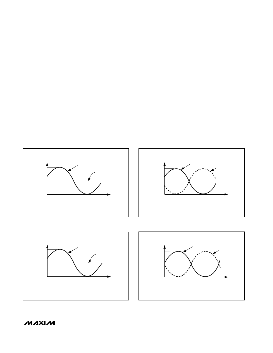
Differential Clock Inputs (Sine-Wave Drive)
The advantages of differential clock drive (Figure 13b,
Table 5) can be obtained by using an appropriate
balun or transformer to convert single-ended sine-wave
sources into differential drives. The precision on-chip,
laser-trimmed 50
Ω
clock-termination resistors ensure
excellent amplitude matching. See
Single-Ended Clock
Inputs (Sine-Wave Drive)
for proper input amplitude
requirements.
Single-Ended Clock Inputs (ECL Drive)
Configure the MAX108 for single-ended ECL clock
drive by connecting the clock inputs as shown in Figure
13c (Table 5). A well-bypassed V
BB
supply (-1.3V) is
essential to avoid coupling noise into the undriven
clock input, which would degrade dynamic perfor-
mance.
Differential Clock Inputs (ECL Drive)
Drive the MAX108 from a standard differential (Figure
13d, Table 5) ECL clock source by setting the clock ter-
mination voltage at CLKCOM to -2V. Bypass the clock-
termination return (CLKCOM) as close to the ADC as
possible with a 0.01µF capacitor connected to GNDI.
MAX108
±5V, 1.5Gsps, 8-Bit ADC with
On-Chip 2.2GHz Track/Hold Amplifier
______________________________________________________________________________________
19
CLK+
CLK- = 0V
+0.5V
-0.5V
NOTE: CLKCOM = 0V
t
Figure 13a. Single-Ended Clock Input Signals
CLK+
CLK-
+0.5V
-0.5V
t
NOTE: CLKCOM = 0V
Figure 13b. Differential Clock Input Signals
CLK+
-0.8V
-1.8V
t
CLK- = -1.3V
NOTE: CLKCOM = -2V
Figure 13c. Single-Ended ECL Clock Drive
CLK+
CLK-
-0.8V
-1.8V
t
NOTE: CLKCOM = -2V
Figure 13d. Differential ECL Clock Drive