Rainbow Electronics MAX108 User Manual
Page 15
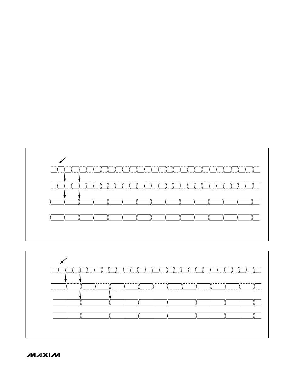
Non-Demultiplexed DIV1 Mode
The MAX108 may be operated at up to 750Msps in
non-demultiplexed DIV1 mode (Table 2). In this mode,
the internal demultiplexer is disabled and sampled
data is presented to the primary port only, with the
data repeated at the auxiliary port but delayed by one
clock cycle (Figure 6). Since the auxiliary output port
contains the same data stream as the primary output
port, the auxiliary port can be shut down to save
power by connecting AUXEN1 and AUXEN2 to digital
ground (GNDD). This powers down the internal bias
cells and causes both outputs (true and complemen-
tary) of the auxiliary port to pull up to a logic-high
level. To save additional power, the external 50
Ω
ter-
mination resistors connected to the PECL termination
power supply (V
CC
O - 2V) may be removed from all
auxiliary output ports.
Demultiplexed DIV2 Mode
The MAX108 features an internally selectable DIV2
mode (Table 2) that reduces the output data rate to
one-half of the sample clock rate. The demultiplexed
outputs are presented in dual 8-bit format with two con-
secutive samples appearing in the primary and auxil-
iary output ports on the rising edge of the data-ready
clock (Figure 7). The auxiliary data port contains the
previous sample, and the primary output contains the
most recent data sample. AUXEN1 and AUXEN2 must
be connected to V
CC
O to power up the auxiliary port
PECL output drives.
MAX108
±5V, 1.5Gsps, 8-Bit ADC with
On-Chip 2.2GHz Track/Hold Amplifier
______________________________________________________________________________________
15
NOTE: THE AUXILIARY PORT DATA IS DELAYED ONE ADDITIONAL CLOCK CYCLE FROM THE PRIMARY PORT DATA.
GROUNDING AUXEN1 AND AUXEN2 WILL POWER DOWN THE AUXILIARY PORT TO SAVE POWER.
CLK-
CLK+
n
n+1
n+2
n+3
n+4
n+5
n+1
n+2
n+3
n+4
n
n+1
n+2
n+3
n+4
n+5
n+6
n+7
n+8
n+9
n+10
n+11
n+12
n+13
ADC SAMPLE NUMBER
ADC SAMPLES ON THE RISING EDGE OF CLK+
CLK
DREADY
AUXILIARY
DATA PORT
PRIMARY
DATA PORT
DREADY+
DREADY-
Figure 6. Non-Demuxed, DIV1-Mode Timing Diagram
NOTE: THE LATENCY TO THE PRIMARY PORT IS 7.5 CLOCK CYCLES, AND THE LATENCY TO THE AUXILIARY PORT IS 8.5 CLOCK CYCLES.
BOTH THE PRIMARY AND AUXILIARY DATA PORTS ARE UPDATED ON THE RISING EDGE OF THE DREADY+ CLOCK.
CLK-
CLK+
n
n+1
n+2
n+3
n+4
n+5
n+1
n-1
n+3
n+6
n+7
n+8
n+9
n+10
n+11
n+12
n+13
ADC SAMPLE NUMBER
ADC SAMPLES ON THE RISING EDGE OF CLK+
CLK
DREADY
AUXILIARY
DATA PORT
PRIMARY
DATA PORT
DREADY+
DREADY-
n
n+2
n+4
Figure 7. Demuxed DIV2-Mode Timing Diagram