Rainbow Electronics MAX194 User Manual
Page 9
If you read the data bits between conversions, you can
1) count CLK cycles until the end of the conversion, or
2) poll EOC to determine when the conversion is
finished, or
3) generate an interrupt on EOC’s falling edge.
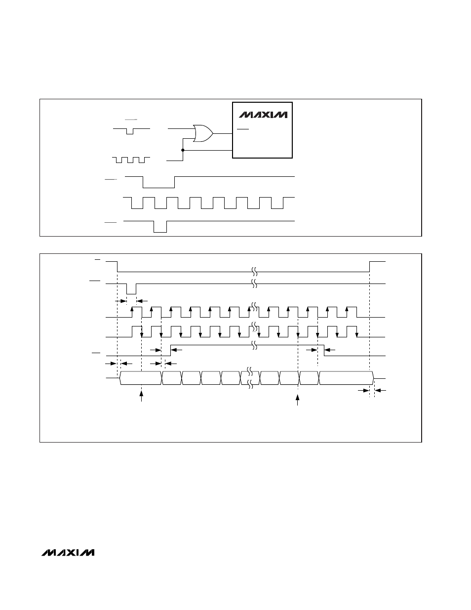
Note that the MSB conversion result appears at DOUT
after CS goes low but
before
the first SCLK pulse. Each
subsequent SCLK pulse shifts out the next conversion
bit. The 15th SCLK pulse shifts out the sub-LSB (S0).
Additional clock pulses shift out zeros.
Data is clocked out on SCLK’s falling edge. Clock data
in on SCLK’s rising edge or, for clock speeds above
2.5MHz, on the following falling edge to meet the maxi-
mum SCLK-to-DOUT timing specification (Figure 7).
The maximum SCLK speed is 5MHz. See the
Operating
Modes and SPI/QSPI Interfaces
section for additional
information. When the conversion clock is near its maxi-
MAX194
14-Bit, 85ksps ADC with 10µA Shutdown
_______________________________________________________________________________________
9
CLK
START
CONV
MAX194
CONV
START
CLK
SEE
DIGITAL INTERFACE SECTION
CS
CONV
CLK
(CASE 1)
CLK
(CASE 2)
EOC
t
DV
t
CD
t
CW
t
CEH
CASE 1: CLK IDLES LOW, DATA LATCHED ON RISING EDGE (CPOL = 0, CPHA = 0)
CASE 2: CLK IDLES LOW, DATA LATCHED ON FALLING EDGE (CPOL = 0, CPHA = 1)
NOTE: ARROWS ON CLK TRANSITIONS INDICATE LATCHING EDGE
t
CEL
DOUT
t
DH
B13
CONVERSION
BEGINS
CONVERSION
ENDS
MSB
LSB
SUB-LSBs
B12
B11
B10
B0
S1
S0
B13
B13 FROM PREVIOUS
CONVERSION
Figure 5. Gating CONV to Synchronize with CLK
Figure 6. Output Data Format, Reading Data During Conversion (Mode 1)