Max194, Bit, 85ksps adc with 10µa shutdown, Calibration – Rainbow Electronics MAX194 User Manual
Page 6
MAX194
Calibration
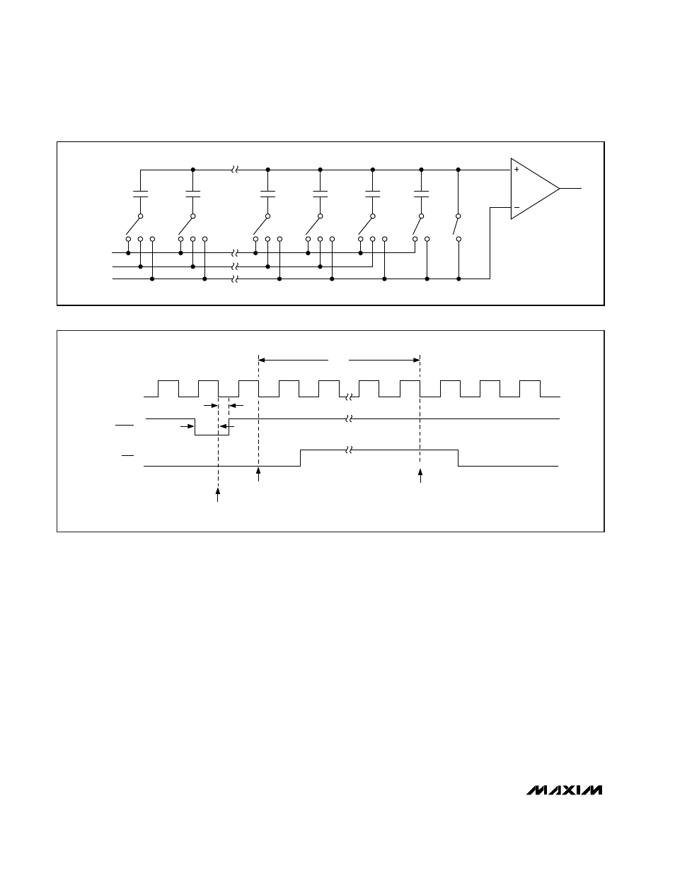
In an ideal DAC, each of the capacitors associated with
the data bits would be exactly twice the value of the
next smaller capacitor. In practice, this results in a
range of values too wide to be realized in an economi-
cally feasible size. The capacitor array actually consists
of two arrays, which are capacitively coupled to reduce
the LSB array’s effective value. The capacitors in the
MSB array are production trimmed to reduce errors.
Small variations in the LSB capacitors contribute
insignificant errors to the 14-bit result.
Unfortunately, trimming alone does not yield 14-bit per-
formance or compensate for changes in performance
due to changes in temperature, supply voltage, and
other parameters. For this reason, the MAX194 includes
a calibration DAC for each capacitor in the MSB array.
These DACs are capacitively coupled to the main DAC
output and offset the main DAC’s output according to
the value on their digital inputs. During calibration, the
correct digital code to compensate for the error in each
MSB capacitor is determined and stored. Thereafter,
the stored code is input to the appropriate calibration
DAC whenever the corresponding bit in the main DAC
is high, compensating for errors in the associated
capacitor.
The MAX194 calibrates automatically on power-up. To
reduce the effects of noise, each calibration experiment
is performed many times and the results are averaged.
Calibration requires about 14,000 clock cycles, or
8.2ms at the highest clock (CLK) speed (1.7MHz). In
addition to the power-up calibration, bringing RESET
low halts MAX194 operation, and bringing it high again
initiates a calibration (Figure 2).
14-Bit, 85ksps ADC with 10µA Shutdown
6
_______________________________________________________________________________________
LSB
MSB
AIN
REF
AGND
DUMMY
SUB-LSBs
32,768C
16,384C
4C
2C
C
C
EOC
CLK
RESET
CALIBRATION
BEGINS
CALIBRATION
ENDS
MAX194
OPERATION HALTS
t
CAL
t
RCS
t
RCH
Figure 1. Capacitor DAC Functional Diagram
Figure 2. Initiating Calibration