Table 1. low-esr capacitor suppliers, Applications information – Rainbow Electronics MAX194 User Manual
Page 11
MAX194
14-Bit, 85ksps ADC with 10µA Shutdown
______________________________________________________________________________________
11
BRIDGE
INSTRUMENTATION
AMPLIFIER
+5V
AIN
MAX194
VDDA
47
µ
F
LOW
ESR
0.1
µ
F
CERAMIC
REF
COMPANY
CAPACITOR
FACTORY FAX [COUNTRY CODE]
USA TELEPHONE
Sprague
595D series,
592D series
[1]-603-224-1430
603-224-1961
AVX
TPS series
[1]-207-283-1941
800-282-4975
Sanyo
OS-CON series,
MV-GX series
[81]-7-2070-1174
619-661-6835
Nichicon
PL series
[1]-708-843-2798
708-843-7500
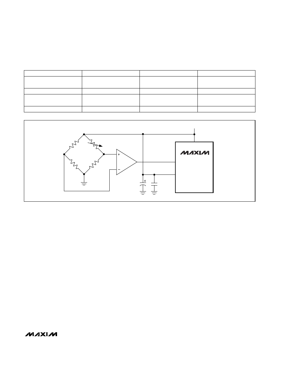
Figure 9. Ratiometric Measurement Without an Accurate Reference
Table 1. Low-ESR Capacitor Suppliers
__________Applications Information
Reference
The MAX194 reference voltage range is 0V to VDDA.
When choosing the reference voltage, the MAX194’s
equivalent input noise (40µV
RMS
in unipolar mode,
80µV
RMS
in bipolar mode) should be considered. Also, if
V
REF
exceeds VDDA, errors will occur due to the internal
protection diodes that will begin to conduct, so use cau-
tion when using a reference near VDDA (unless V
REF
and VDDA are virtually identical). V
REF
must never
exceed its absolute maximum rating (VDDA + 0.3V).
The MAX194 needs a good reference to achieve its
rated performance. The most important requirement is
that the reference must present a low impedance to the
REF input. This is often achieved by buffering the refer-
ence through an op amp and bypassing the REF input
with a large (1µF to 47µF), low-ESR capacitor in parallel
with a 0.1µF ceramic capacitor. Low-ESR capacitors
are available from the manufacturers listed in Table 1.
The reference must drive the main conversion DAC
capacitors as well as the capacitors in the calibration
DACs, all of which may be switching between GND and
REF at the conversion clock frequency. The total
capacitive load presented can exceed 1000pF and,
unlike the analog input (AIN), REF is sampled continu-
ously throughout the conversion.
The first step in choosing a reference circuit is to
decide what kind of performance is required. This often
suggests compromises made in the interests of cost
and size. It is possible that a system may not require an
accurate reference at all. If a system makes a ratiomet-
ric measurement such as Figure 9’s bridge circuit, any
relatively noise-free voltage that presents a low imped-
ance at the REF input will serve as a reference. The
+5V analog supply suffices if you use a large, low-
impedance bypass capacitor to keep REF stable dur-
ing switching of the capacitor arrays. Do not place a
resistance between the +5V supply and the bypass
capacitor, because it will cause linearity errors due to
the dynamic REF input current, which typically ranges
from 300µA to 400µA.
Figure 10 shows a more typical scheme that provides
good AC accuracy. The MAX874’s initial accuracy can