Spurious-free dynamic range, Transfer function – Rainbow Electronics MAX194 User Manual
Page 24
MAX194
14-Bit, 85ksps ADC with 10µA Shutdown
Spurious-Free Dynamic Range
Spurious-free dynamic range is the ratio of the funda-
mental RMS amplitude to the amplitude of the next
largest spectral component (in the frequency band
above DC and below one-half the sample rate). Usually,
this peak occurs at some harmonic of the input frequen-
cy. However, if the ADC is exceptionally linear, it may
occur only at a random peak in the ADC’s noise floor.
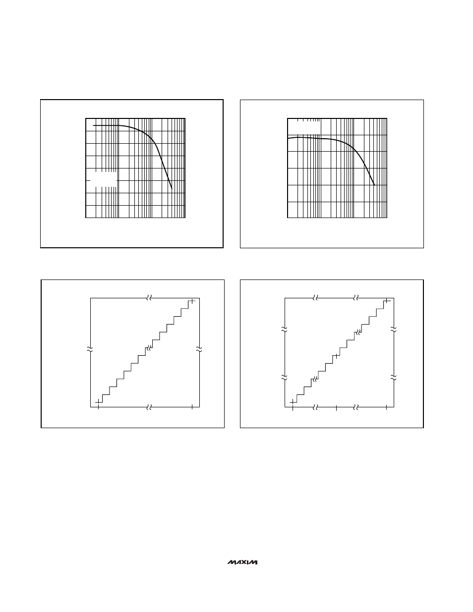
Transfer Function
Figures 28 and 29 show the MAX194’s transfer func-
tions. In unipolar mode, the output data is in binary for-
mat and in bipolar mode it is offset binary.
TRANSISTOR COUNT: 7966
11 . . . 111
11 . . . 110
11 . . . 101
11 . . . 100
11 . . . 011
11 . . . 010
00 . . . 110
00 . . . 101
00 . . . 100
00 . . . 011
00 . . . 010
00 . . . 001
00 . . . 000
0V
V
REF
- (1LSB)
11 . . . 111
11 . . . 110
11 . . . 101
10 . . . 010
10 . . . 001
10 . . . 000
01 . . . 111
01 . . . 110
00 . . . 010
00 . . . 001
00 . . . 000
-V
REF
V
REF
- (1LSB)
0V
Figure 28. MAX194 Unipolar Transfer Function
Figure 29. MAX194 Bipolar Transfer Function
90
60
0.1
10
100
65
70
75
80
85
MAX194-27
FREQUENCY (kHz)
SINAD (dB)
1
f
S
= 85kHz
T
A
= +25°C
10.0
11.0
10.5
11.5
12.0
12.5
13.0
14.0
13.5
0.1
1
10
100
MAX194-26
INPUT FREQUENCY (kHz)
EFFECTIVE BITS
f
S
= 85kHz
T
A
= +25°C
Figure 27. Signal-to-Noise + Distortion vs. Frequency
Figure 26. Effective Bits vs. Input Frequency
Maxim cannot assume responsibility for use of any circuitry other than circuitry entirely embodied in a Maxim product. No circuit patent licenses are
implied. Maxim reserves the right to change the circuitry and specifications without notice at any time.
24
____________________Maxim Integrated Products, 120 San Gabriel Drive, Sunnyvale, CA 94086 408-737-7600
© 1997 Maxim Integrated Products
Printed USA
is a registered trademark of Maxim Integrated Products.