Max194, Bit, 85ksps adc with 10µa shutdown, Ref and ain input protection – Rainbow Electronics MAX194 User Manual
Page 14: Analog input
MAX194
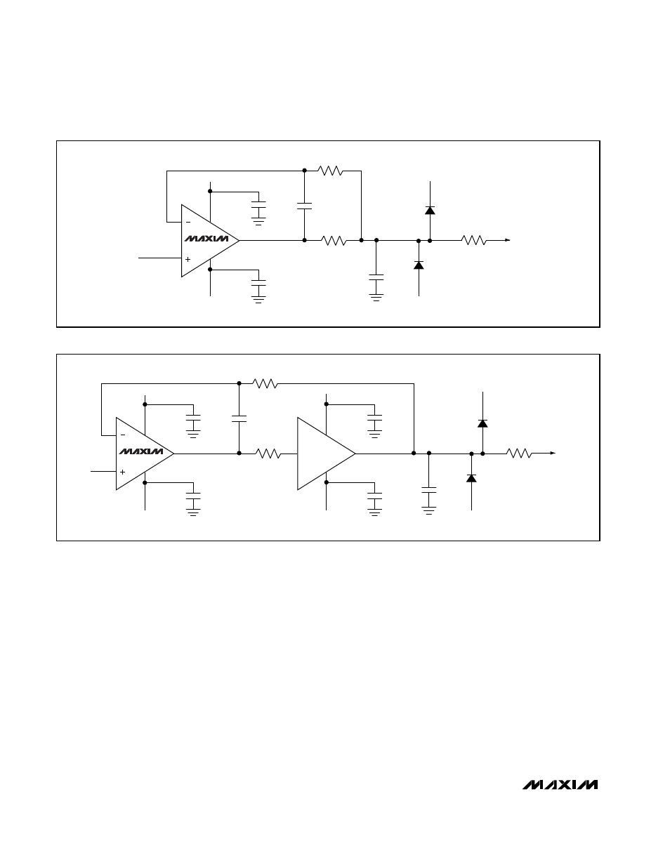
REF and AIN Input Protection
The REF and AIN signals should not exceed the
MAX194 supply rails. If this can occur, diode clamp the
signal to the supply rails. Use silicon diodes and a 10
Ω
current-limiting resistor (Figures 10 and 12) or Schottky
diodes without the resistor.
When using the current-limiting resistor, place the resis-
tor between the appropriate input (AIN or REF) and any
bypass capacitor. While this results in AC transients at
the input due to dynamic input currents, the transients
settle quickly and do not affect conversion results.
Improperly placing the bypass capacitor directly at the
input forms an RC lowpass filter with the current-limiting
resistor, which averages the dynamic input current and
causes linearity errors.
Analog Input
The MAX194 uses a capacitive DAC that provides an
inherent track/hold function. The input impedance is
typically 30
Ω
in series with 250pF in unipolar mode and
50
Ω
in series with 125pF in bipolar mode.
Input Range
The analog input range can be either unipolar (0V to
V
REF
) or bipolar (-V
REF
to V
REF
), depending on the
state of the BP/UP/SHDN pin (see
Digital Interface
sec-
tion). The reference range is 0V to VDDA. When choos-
ing the reference voltage, the equivalent MAX194 input
noise (40µV
RMS
in unipolar mode, 80µV
RMS
in bipolar
mode) should be considered.
14-Bit, 85ksps ADC with 10µA Shutdown
14
______________________________________________________________________________________
MAX427
4
7
6
2
2
3
IN
+15V
-15V
0.0033
µ
F
0.1
µ
F
0.1
µ
F
ELANTEC
EL2003
4
1
7
+15V
-15V
0.1
µ
F
0.1
µ
F
100pF
1k
1k
1N914
1N914
+5V
-5V
AIN
10
Ω
MAX400
4
7
6
2
3
IN
+15V
-15V
1.0
µ
F
0.1
µ
F
0.1
µ
F
1000pF
1k
100
Ω
AIN
1N914
1N914
+5V
-5V
10
Ω
Figure 14. MAX400 Drives AIN for Low-Frequency Use
Figure 15. AIN Buffer for AC/DC Use