Electrical characteristics (continued), Electrical characteristics – Rainbow Electronics MAX1813 User Manual
Page 5
MAX1813
Dynamically-Adjustable, Synchronous Step-Down
Controller with Integrated Voltage Positioning
_______________________________________________________________________________________
5
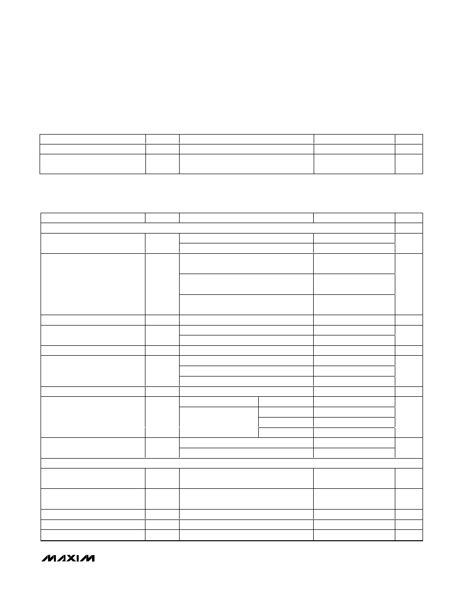
ELECTRICAL CHARACTERISTICS (continued)
(Circuit of Figure 1, V+ = +15V, V
CC
= V
DD
= 5V, VPCS = ZMODE = GND = PGND, SKP/SDN = CODE = V
CC
, V
OUT
set to 1.5V,
T
A
= 0
°C to +85°C, unless otherwise noted. Typical values are at T
A
= +25
°C.)
ELECTRICAL CHARACTERISTICS
(Circuit of Figure 1, V+ = +15V, V
CC
= V
DD
= 5V, VPCS = ZMODE = GND = PGND, SKP/SDN = CODE = V
CC
, V
OUT
set to 1.5V,
T
A
= -40
°C to +85°C, unless otherwise noted.) (Note 5)
PARAMETER
SYMBOL
CONDITIONS
MIN
TYP
MAX
UNITS
SKP/SDN NO FAULT Input Level
12
15
V
SKP/SDN, 4-Level Logic Input
Current
SKP/SDN, TON, S0, S1 = GND or V
CC
-3
3
µA
PARAMETER
SYMBOL
CONDITIONS
MIN
MAX
UNITS
PWM CONTROLLER
Battery voltage, V+
2
28
Input Voltage Range
V
CC
, V
DD
4.5
5.5
V
V+ = 4.5V to 28V, VPCS = GND, DAC
codes from 0.925V to 2.0V
-1
+1
V+ = 4.5V to 28V, VPCS = GND, DAC
codes from 0.700V to 0.900V
-1.5
+1.5
DC Output Voltage Accuracy
(Notes 2, 3)
V+ = 4.5V to 28V, VPCS = GND, DAC
codes from 0.600V to 0.675V
-1.83
+1.83
%
VPCS Input Bias Current
I
VPS
V
VPCS
= 0 or 28V
-1
+1
µA
V
VPS
= 0 to -40mV
18
22
VPCS Transconductance
G
m
V
VPS
= 0 to -100mV
16.5
22
µS
FB Input Resistance
R
FB
115
265
k
Ω
380kHz nominal, R
TIME
= 47k
Ω
-12
+12
150kHz nominal, R
TIME
= 120k
Ω
-8
+8
TIME Frequency Accuracy
38kHz nominal, R
TIME
= 470k
Ω
-12
+12
%
ILIM Input Leakage Current
I
ILIM
V
ILIM
= 0 or 5.0V
100
nA
V+ = 5.0V, V
FB
= 1.2V
TON = GND
250
290
TON = REF
165
215
TON = open
320
390
On-Time (Note 4)
t
ON
V+ = 12V, V
FB
= 1.2V
TON = V
CC
465
563
ns
TON = REF, open, or V
CC
500
Minimum Off-Time (Note 4)
t
OFF(M IN)
TON = GND
375
ns
BIAS AND REFERENCE
Quiescent Supply Current (V
CC
)
I
CC
Measured at V
CC
, FB forced above the
regulation point
2.5
mA
Quiescent Supply Current (V
DD
)
I
DD
Measured at V
DD
, FB forced above the
regulation point
5
µA
Quiescent Supply Current (V+)
I+
Measured at V+
40
µA
Shutdown Supply Current (V
CC
)
SKP/SDN = GND
5
µA
Shutdown Supply Current (V
DD
)
SKP/SDN = GND
5
µA