Detailed description, 5v bias supply (v, And v – Rainbow Electronics MAX1813 User Manual
Page 14
MAX1813
Dynamically-Adjustable, Synchronous Step-Down
Controller with Integrated Voltage Positioning
14
______________________________________________________________________________________
Detailed Description
The MAX1813 buck controller is targeted for low-volt-
age, high-current CPU core power supplies for note-
book computers, which typically exhibit 0 to 22A (or
greater) load steps. The proprietary Quick-PWM pulse-
width modulator in the converter is specifically
designed for handling fast load steps while maintaining
a relatively constant operating frequency and inductor
operating point over a wide range of input voltages.
The Quick-PWM architecture circumvents the poor
load-transient timing problems of fixed-frequency cur-
rent-mode PWMs while also avoiding the problems
caused by widely varying switching frequencies in con-
ventional constant on-time and constant off-time PFM
schemes.
+5V Bias Supply (V
CC
and V
DD
)
The MAX1813 requires an external +5V bias supply in
addition to the battery. Typically, this +5V bias supply
is the notebook’s 95% efficient +5V system supply.
Keeping the bias supply external to the IC improves
efficiency and eliminates the cost associated with the
+5V linear regulator that would otherwise be needed to
supply the PWM circuit and gate drivers. If stand-alone
capability is needed, the +5V supply can be generated
with an external linear regulator.
The +5V bias supply powers V
CC
(PWM controller) and
V
DD
(gate-drive power). The maximum current is:
I
BIAS
= I
CC
+ ƒ
SW
(Q
G1
+ Q
G2
) = 15mA to 45mA (typ)
where I
CC
is 1.4mA (typ), ƒ
SW
is the switching frequen-
cy, and Q
G1
and Q
G2
are the MOSFET total gate-
charge specification limits at V
GS
= 5V.
The battery input (V+) and +5V bias inputs (V
CC
and
V
DD
) can be connected together if the input source is a
fixed 4.5V to 5.5V supply. If the +5V bias supply is
powered up prior to the battery supply, the enable sig-
nal (SKP/SDN) must be delayed until the battery volt-
age is present in order to ensure startup.
Free-Running, Constant-On-Time PWM
Controller with Input Feed-Forward
The Quick-PWM control architecture is a constant-on-
time, current-mode type with voltage feed-forward
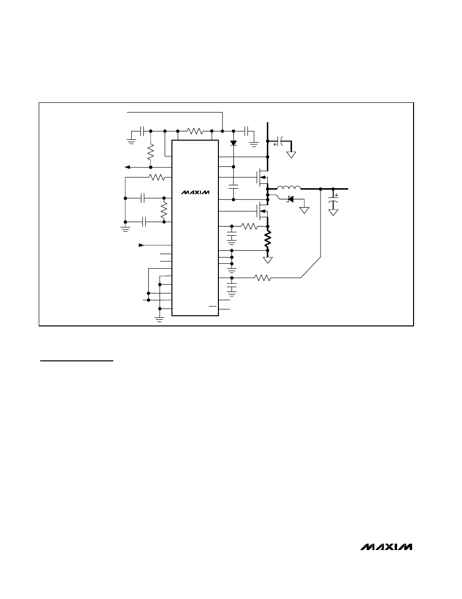
V
CC
C
OUT
D2
L1
0.68
µH
1.4V OUTPUT
UP TO 22A
PGOOD
ILIM
D1
C2
1
µF
C
BST
0.1
µF
Q
H
Q
L
C1
1
µF
R1
20
Ω
C
IN
BATTERY (V
BATT
)
7V TO 24V
CC
TIME
+5V INPUT
BIAS SUPPLY
POWER-GOOD
INDICATOR
DL
LX
V+
DH
BST
VPCS
PGND
GND
ZMODE
FB
TON
V
DD
MAX1813
REF
SUS
S1
S0
D0
CODE
D2
D1
D3
D4
TO V
CC
OPEN
SUSPEND
MODE
OPEN
R
GATE
100k
Ω
R
TIME
120k
Ω
R
AVPS
150k
Ω
C
REF
0.22
µF
C
COMP
47pF
OPEN (FORCED-PWM)
OPEN (300kHz)
R
SENSE
R
VPCS
100
Ω
R
FB
100
Ω
C
VPCS
1nF
C
FB
1nF
SKP/SDN
NOTE: SEE TABLE 1 FOR COMPLETE
LIST OF COMPONENT VALUES
Figure 1. Standard High-Power Application Circuit