Typical operating circuit, Chip information – Rainbow Electronics MAX1813 User Manual
Page 37
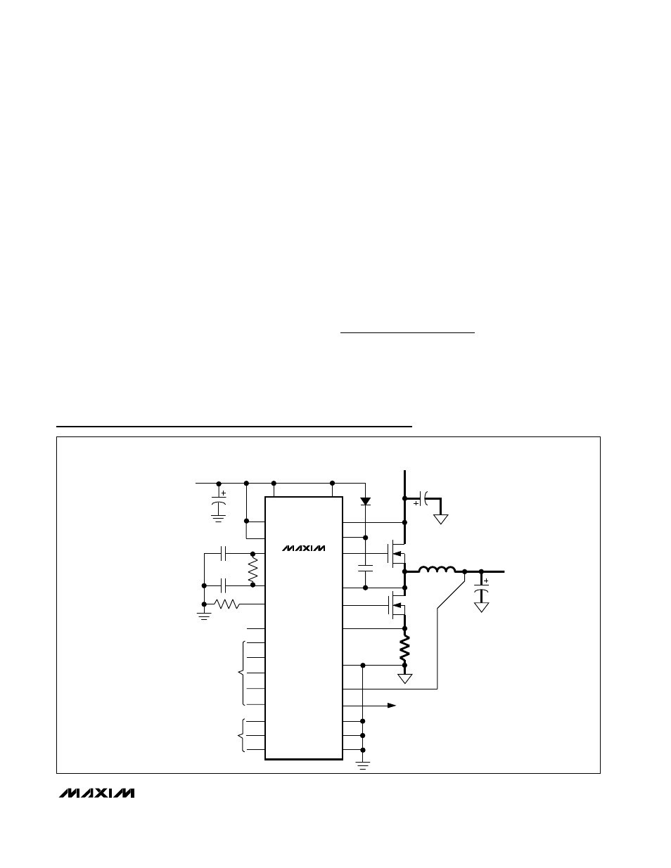
MAX1813
Dynamically-Adjustable, Synchronous Step-Down
Controller with Integrated Voltage Positioning
______________________________________________________________________________________
37
V
CC
OUTPUT
0.925V TO 1.6V
BATTERY
2V TO 28V
+5V INPUT
MAX1813
ILIM
CC
TIME
TON
LX
V+
DH
BST
VPCS
PGND
GND
ZMODE
DL
SUS
V
CC
REF
S1
S0
D0
D2
D1
D3
D4
SKIP
V
DD
FB
PGOOD
CODE
DAC
INPUTS
SUSPEND
MODE
Typical Operating Circuit
Layout Procedure
1) Place the power components first, with ground ter-
minals adjacent (low-side MOSFET source, C
IN
,
C
OUT
, and D1 anode). If possible, make all these
connections on the top layer with wide, copper-filled
areas.
2) Mount the controller IC adjacent to the low-side
MOSFET. The DL gate trace must be short and wide
(50mils to 100mils wide if the MOSFET is 1 inch from
the controller IC).
3) Group the gate-drive components (BST diode and
capacitor, V
DD
bypass capacitor) together near the
controller IC.
4) Make the DC-DC controller ground connections as
shown in Figure 19. This diagram can be viewed as
having three separate ground planes: output
ground, where all the high-power components go;
the power ground plane, where the PGND pin and
V
DD
bypass capacitor go; and an analog ground
plane where sensitive analog components, the GND
pin, and V
CC
bypass capacitor go. The GND plane
and PGND plane must meet only at a single point
directly beneath the IC. These two planes are then
connected to the high-power output ground with a
short connection from PGND to the source of the
low-side MOSFET (the middle of the star ground).
This point must also be very close to the output
capacitor ground terminal.
5) Connect the output power planes (V
CORE
and sys-
tem ground planes) directly to the output filter
capacitor positive and negative terminals with multi-
ple vias. Place the entire DC-DC converter circuit as
close to the CPU as is practical.
Chip Information
TRANSISTOR COUNT: 8757