Electrical characteristics (continued) – Rainbow Electronics MAX1813 User Manual
Page 3
MAX1813
Dynamically-Adjustable, Synchronous Step-Down
Controller with Integrated Voltage Positioning
_______________________________________________________________________________________
3
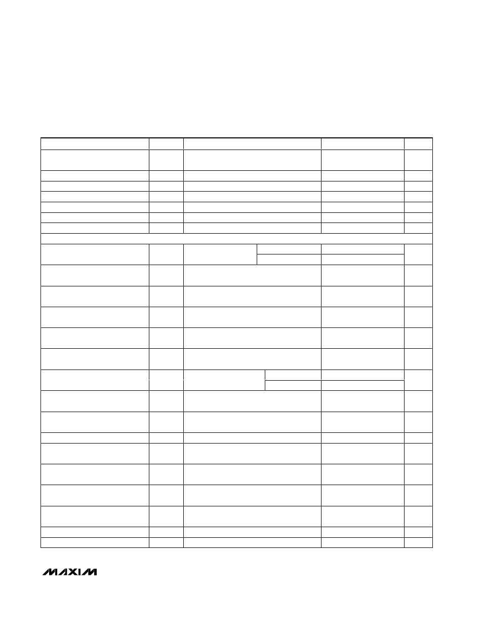
ELECTRICAL CHARACTERISTICS (continued)
(Circuit of Figure 1, V+ = +15V, V
CC
= V
DD
= 5V, VPCS = ZMODE = GND = PGND, SKP/SDN = CODE = V
CC
, V
OUT
set to 1.5V,
T
A
= 0
°C to +85°C, unless otherwise noted. Typical values are at T
A
= +25
°C.)
PARAMETER
SYMBOL
CONDITIONS
MIN
TYP
MAX
UNITS
Quiescent Supply Current (V
DD
)
I
DD
Measured at V
DD
, FB forced above the
regulation point
<1
5
µA
Quiescent Supply Current (V+)
I+
Measured at V+
25
40
µA
Shutdown Supply Current (V
CC
)
SKP/SDN = GND
2
5
µA
Shutdown Supply Current (V
DD
)
SKP/ SDN = GND
<1
5
µA
Shutdown Supply Current (V+)
SKP/SDN = GND, V
CC
= V
DD
= 0 or 5V
<1
5
µA
Reference Voltage
V
REF
V
CC
= 4.5V to 5.5V, -40
µA ≤ I
REF
≤ +40µA
1.98
2
2.02
V
REF Fault Lockout Voltage
Falling edge, 1% hysteresis
1.5
1.6
1.7
V
FAULT PROTECTION
CODE = GND
2.20
2.25
2.30
Output Overvoltage Fault Preset
Threshold
V
OVP
Measured at FB
CODE = V
CC
1.95
2.00
2.05
V
Output Overvoltage Fault
Propagation Delay
t
OVP
FB forced to 2% above trip threshold
1.5
µs
Output Undervoltage Fault
Threshold
With respect to unloaded output voltage
60
70
80
%
Output Undervoltage Fault
Propagation Delay
FB forced to 2% below trip threshold
10
µs
Output Undervoltage Fault-
Blanking Time
From SKP/SDN signal going high, clock
speed set by R
TIME
256
clks
Current-Limit Threshold (Positive,
Default)
V
ITH
V
GND
- V
VPCS
, ILIM = V
CC
40
50
60
mV
V
ILIM
= 0.5V
40
50
60
Current-Limit Threshold
(Positive, Adjustable)
V
ITH
V
GND
- V
VPCS
V
ILIM
= 2V (REF)
143
200
265
mV
Negative Current-Limit Threshold
V
GND
- V
VPCS
, with respect to V
ITH
, ILIM =
V
CC
-72
-56
-40
mV
Zero-Crossing Current-Limit
Threshold
V
GND
- V
VPCS
5
mV
Thermal Shutdown Threshold
Rising temperature, hysteresis = 15°C
160
°C
V
CC
Undervoltage Lockout
Threshold
Rising edge, hysteresis = 20mV, switching
disabled below this level
4.05
4.45
V
PGOOD Lower Trip Threshold
Measured at FB with respect to unloaded
output voltage, falling edge
-15
-12.5
-10.5
%
PGOOD Upper Trip Threshold
Measured at FB with respect to unloaded
output voltage, rising edge
8
10
12
%
PGOOD Propagation Delay
Falling edge, FB forced 2% below or
above PGOOD trip threshold
1.5
µs
PGOOD Output Low Voltage
I
SINK
= 1mA
0.4
V
PGOOD Leakage Current
High state, forced to 5.5V
1
µA