Pin description – Rainbow Electronics MAX1813 User Manual
Page 12
MAX1813
Dynamically-Adjustable, Synchronous Step-Down
Controller with Integrated Voltage Positioning
12
______________________________________________________________________________________
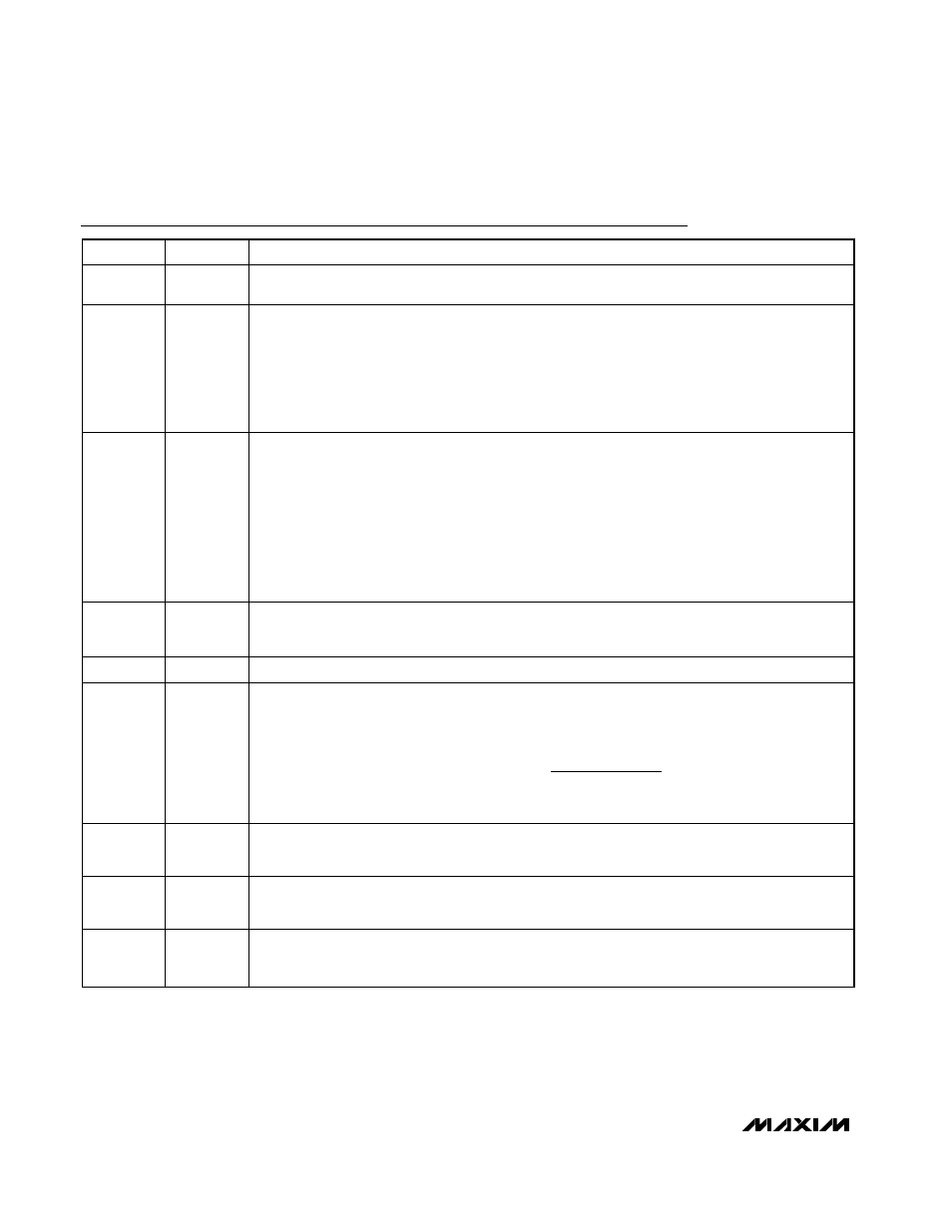
Pin Description
PIN
NAME
FUNCTION
1
V+
Battery Voltage Sense Connection. Connect V+ to the input power source. V+ is used only for PWM
one-shot timing. DH on-time is inversely proportional to the input voltage over a 2V to 28V range.
2
VPCS
Current-Sense Input. Connect a current-sense resistor (R
SENSE
) between VPCS and PGND. The
voltage on VPCS controls both the voltage-positioning and current-limit circuits. The slope of the
voltage-positioned output is controlled with the current-sense resistor and the gain resistor connected
between CC and REF. See Setting Voltage Positioning. The current-limit threshold is set by ILIM. If the
current-sense signal (inductor current
× R
SENSE
) exceeds the current-limit threshold, the MAX1813
will not initiate a new cycle. VPCS can also be connected to LX to reduce component count, but CC
must be connected to REF to disable the voltage positioning.
3
SKP/SDN
Combined Shutdown and Skip-Mode Control. Drive SKP/SDN to GND for shutdown, leave SKP/SDN
open for low-noise forced-PWM mode, or drive to V
CC
for normal pulse-skipping operation:
Shutdown mode: SKP/SDN = GND
Low-noise forced-PWM mode: SKP/SDN = open
Normal pulse-skipping operation: SKP/SDN = V
CC
Low-noise forced PWM mode causes inductor current recirculation at light loads and suppresses
pulse-skipping operation. Forcing SKP/SDN with 12V to 15V clears the fault latch and disables
undervoltage protection, overvoltage protection, and thermal shutdown with otherwise normal pulse-
skipping operation. Exiting shutdown clears the fault latch.
Do not connect SKP/SDN to voltages over 15V.
4
TIME
Slew-Rate Adjustment Pin. Connect a resistor from TIME to GND to set the internal slew-rate clock. A
470k
Ω to 47kΩ resistor sets the clock from 38kHz to 380kHz, respectively:
f
SLEW
= 150kHz x 120k
Ω / R
TIME
.
5
FB
Feed b ack Inp ut. C onnect FB to the j uncti on of the exter nal i nd uctor and outp ut cap aci tor ( Fi g ur e 1) .
6
CC
Compensation Capacitor and Voltage-Positioning Gain Adjustment. Connect a 47pF to 1000pF (47pF
typ) capacitor from CC to GND to adjust the loop’s response time. Connect a resistor (R
AVPS
) from
CC to REF to set the gain of the voltage positioning amplifier.
where the voltage-positioning amplifer’s transconductance (G
m
) is typically 20
µS.
7, 8
S0, S1
Suspend-Mode Voltage Select Inputs. S0 and S1 are 4-level logic inputs that select the suspend-
mode VID code for for the suspend-mode multiplexer inputs. If SUS is high, the suspend-mode VID
code is delivered to the DAC. See Suspend-Mode Internal Mux.
9
V
CC
Analog Supply Voltage Input for PWM Core. Connect V
CC
to the system supply voltage (4.5V to 5.5V)
through a series 20
Ω resistor. Bypass to GND with a 0.22µF or greater capacitor as close to the
MAX1813 as possible.
10
TON
On-Time Selection-Control Input. This is a 4-level input used to determine DH on-time. Connect to
GND, REF, or V
CC
, or leave TON unconnected to set the following switching frequencies: GND =
1000kHz, REF = 600kHz, floating = 300kHz, and V
CC
= 200kHz.
V
V
G R
V
V
OUT
OUT PROG
m AVPS VPCS
REF
=
+
(
)
1