Loop-powered, 4–20ma transmitters, Power supplies – Rainbow Electronics MAX1401 User Manual
Page 34
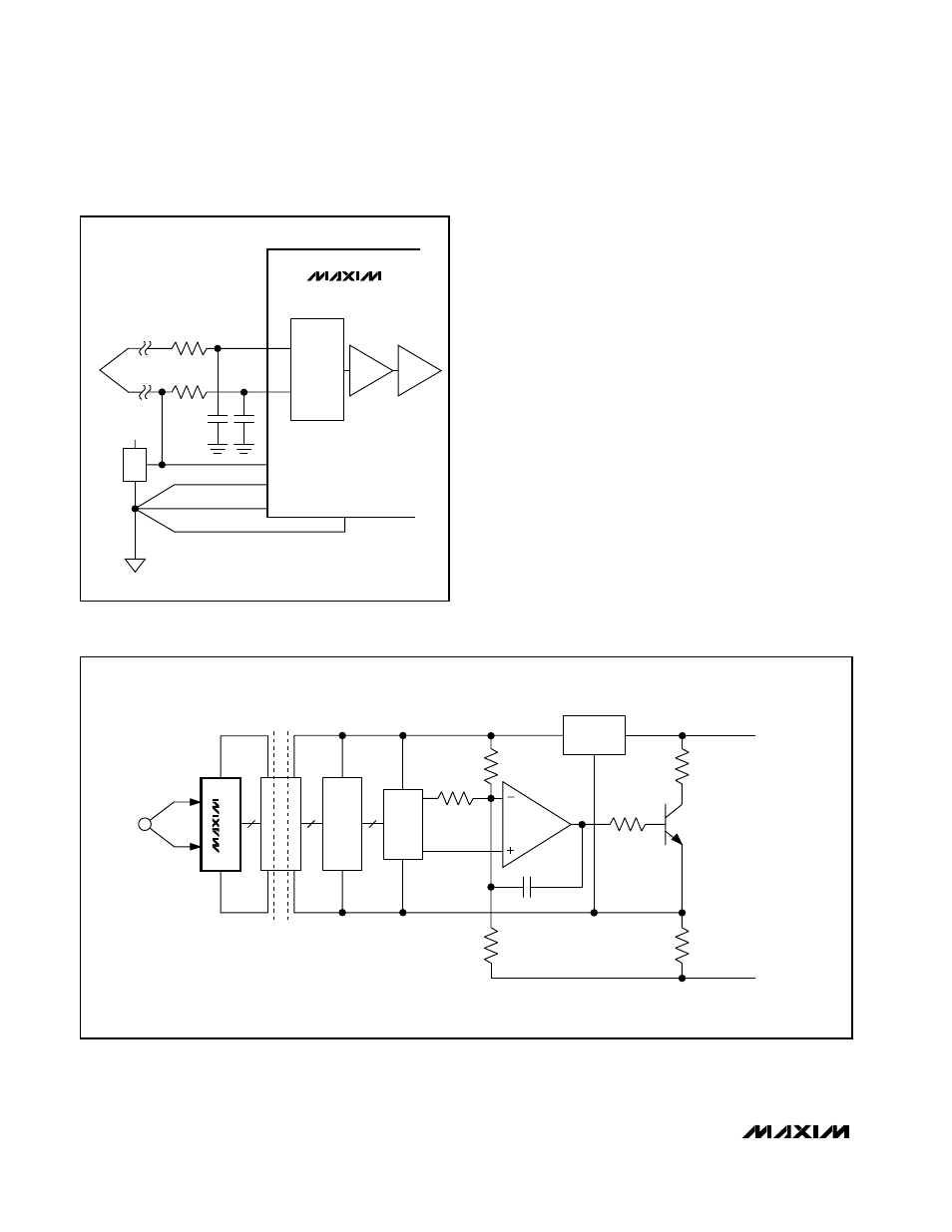
Loop-Powered, 4–20mA Transmitters
Low power, single-supply operation, and easy interfac-
ing with optocouplers make the MAX1401 ideal for
loop-powered 4–20mA transmitters. Loop-powered
transmitters draw their power from the 4–20mA loop,
limiting the transmitter circuitry to a current budget of
4mA. Tolerances in the loop further limit this current
budget to 3.5mA. Since the MAX1401 consumes only
250µA, a total of 3.25mA remains to power the remain-
ing transmitter circuitry. Figure 16 shows a block dia-
gram for a loop-powered 4–20mA transmitter.
Power Supplies
No specific power sequence is required for the
MAX1401; either the V+ or the V
DD
supply can come
up first. While the latchup performance of the MAX1401
is good, to avoid latchup it is important that power be
applied to the MAX1401 before the analog input signals
(AIN_) or the CLKIN inputs. If this is not possible, then
the current flow into any of these pins should be limited
to 50mA. If separate supplies are used for the
MAX1401 and the system digital circuitry, then the
MAX1401 should be powered up first.
MAX1401
+3V, 18-Bit, Low-Power, Multichannel,
Oversampling (Sigma-Delta) ADC
34
______________________________________________________________________________________
DAC
R
GAIN
R
OFST
R
X
V
IN+
V
IN-
R
SENSE
4–20mA LOOP
INTERFACE
R
FDBK
R
Y
C
C
ISOLATION
BARRIER
V+
GND
V+
4
SPI
4
SPI
3
SPI
GND
SENSOR
VOLTAGE
REGULATOR
µ
P/
µ
C
MAX1401
Figure 16. 4–20mA Transmitter
C
C
+3V
+1.25V
REFIN+
REFIN-
AGND
DGND
R
R
THERMOCOUPLE
JUNCTION
SWITCHING
NETWORK
PGA
BUFFER
AIN1
AIN2
MAX1401
Figure 15. Thermocouple Application with MAX1401