Applications information, Analog filtering, Calibration channels – Rainbow Electronics MAX1401 User Manual
Page 30
MAX1401
+3V, 18-Bit, Low-Power, Multichannel,
Oversampling (Sigma-Delta) ADC
30
______________________________________________________________________________________
input can be up to four-times the output data period.
For a synchronized step input (using the FSYNC func-
tion or the internal scanning logic), the settling time is
three-times the output data period.
Analog Filtering
The digital filter does not provide any rejection close to
the harmonics of the modulator sample frequency.
However, due to the high oversampling ratio of the
MAX1401, these bands occupy only a small fraction of
the spectrum, and most broadband noise is filtered.
Therefore, the analog filtering requirements in front of
the MAX1401 are considerably reduced compared to a
conventional converter with no on-chip filtering. In addi-
tion, because the part’s common-mode rejection of
90dB extends out to several kilohertz, common-mode
noise susceptibility in this frequency range is substan-
tially reduced.
Depending on the application, it may be necessary to
provide filtering prior to the MAX1401 to eliminate
unwanted frequencies the digital filter does not reject. It
may also be necessary in some applications to provide
additional filtering to ensure that differential noise sig-
nals outside the frequency band of interest do not satu-
rate the analog modulator.
If passive components are placed in front of the
MAX1401, when the part is used in unbuffered mode,
ensure that the source impedance is low enough not to
introduce gain errors in the system (Tables 13a–13d).
This can significantly limit the amount of passive anti-
aliasing filtering that can be applied in front of the
MAX1401 in unbuffered mode. However, when the part
is used in buffered mode, large source impedances will
simply result in a small DC offset error (a 1k
Ω
source
resistance will cause an offset error of less than 10µV).
Therefore, where any significant source impedances are
required, Maxim recommends operating the part in
buffered mode.
Calibration Channels
Two fully differential calibration channels allow mea-
surement of the system gain and offset errors. Connect
the CALOFF channel to 0V and the CALGAIN channel
to the reference voltage. Average several measure-
ments on both CALOFF and CALGAIN. Subtract the
average offset code and scale to correct for the gain
error. This linear calibration technique can be used to
remove errors due to source impedances on the analog
input (e.g., when using a simple RC anti-aliasing filter
on the front end).
Applications Information
SPI Interface (68HC11, PIC16C73)
Microprocessors with a hardware SPI (serial peripheral
interface) can use a 3-wire interface to the MAX1401
(Figure 12). The SPI hardware generates groups of
eight pulses on SCLK, shifting data in on one pin and
out on the other pin.
For best results, use a hardware interrupt to monitor the
INT pin and acquire new data as soon as it is available.
If hardware interrupts are not available, or if interrupt
latency is longer than the selected conversion rate, use
the FSYNC bit to prevent automatic measurement while
reading the data output register.
The example code in Listing 1 shows how to interface
with the MAX1401 using a 68HC11. System-dependent
initialization code is not shown.
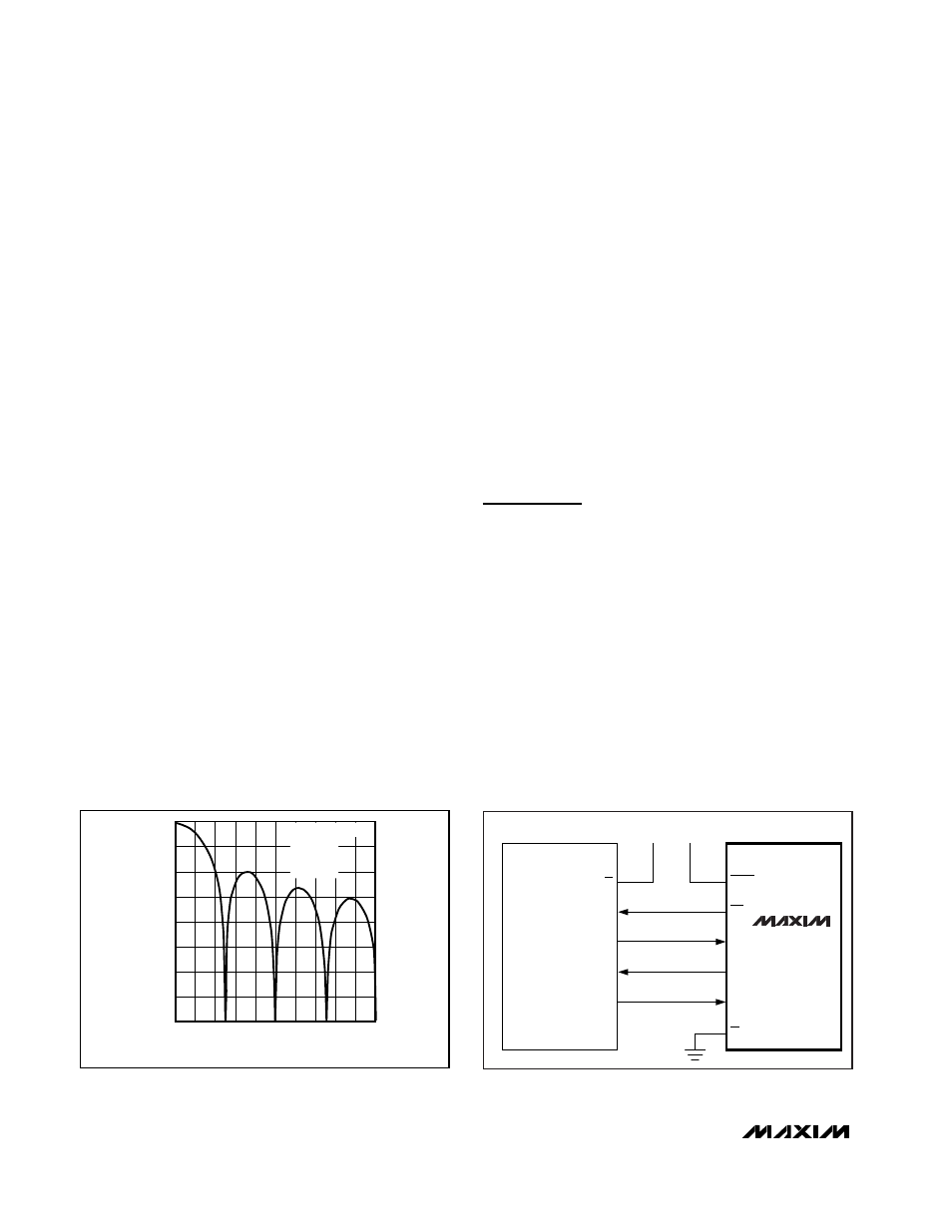
-160
-140
-100
-120
-80
-60
-20
-40
0
0
40 60 80
20
100 120 140 160 180 200
FREQUENCY (Hz)
GAIN (dB)
f
CLKIN
= 2.4576MHz
MF1, 0 = 0
FS1, 0 = 0
f
N
= 50Hz
Figure 11. Frequency Response of the SINC
3
Filter (Notch at
50Hz)
V
DD
SS
INTERRUPT
SCK
MISO
MOSI
RESET
INT
SCLK
DOUT
DIN
CS
V
DD
68HC11
MAX1401
Figure 12. MAX1401 to 68HC11 Interface