Strain-gauge operation, Temperature measurement – Rainbow Electronics MAX1401 User Manual
Page 33
MAX1401
+3V, 18-Bit, Low-Power, Multichannel,
Oversampling (Sigma-Delta) ADC
______________________________________________________________________________________
33
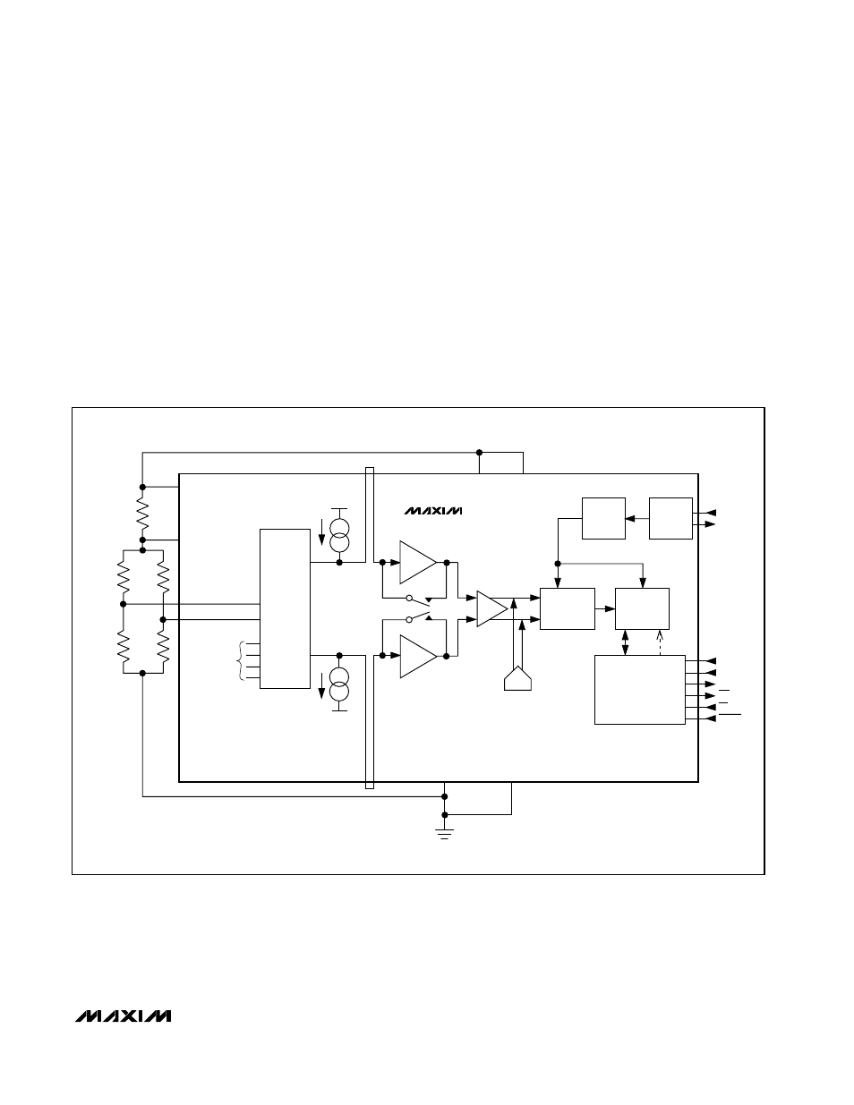
Strain-Gauge Operation
Connect the differential inputs of the MAX1401 to the
bridge network of the strain gauge. In Figure 14, the
analog positive supply voltage powers the bridge net-
work and the MAX1401 along with its reference voltage.
The on-chip PGA allows the MAX1401 to handle an
analog input voltage range as low as 10mV full scale.
The differential inputs of the part allow this analog input
range to have an absolute value anywhere between
AGND and V+.
Temperature Measurement
Figure 15 shows a connection from a thermocouple to
the MAX1401. In this application, the MAX1401 is oper-
ated in its buffered mode to allow large decoupling
capacitors on the front end. These decoupling capaci-
tors eliminate any noise pickup from the thermocouple
leads. When the MAX1401 is operated in buffered mode,
it has a reduced common-mode range. In order to place
the differential voltage from the thermocouple on a suit-
able common-mode voltage, the AIN2 input of the
MAX1401 is biased at the reference voltage, +1.25V.
DIVIDER
CLOCK
GEN
MODULATOR
DIGITAL
FILTER
V+
V+
V
DD
AGND
REFIN+
MUXOUT+
ADCIN+
REFIN-
MUXOUT-
ADCIN-
AGND
DGND
AIN1
AIN2
SWITCHING
NETWORK
ACTIVE
GAUGE
DUMMY
GAUGE
R
REF
ANALOG SUPPLY
R
R
ADDITIONAL
ANALOG
AND
CALIBRATION
CHANNELS
INTERFACE
AND
CONTROL
SCLK
DIN
DOUT
INT
CS
RESET
CLKIN
CLKOUT
PGA
DAC
MAX1401
BUFFER
BUFFER
Figure 14. Strain-Gauge Application with MAX1401