Rainbow Electronics MAX1718 User Manual
Page 23
MAX1718
Notebook CPU Step-Down Controller for Intel
Mobile Voltage Positioning (IMVP-II)
______________________________________________________________________________________
23
voltage. If the output is more than 2V, OVP is triggered
and the circuit shuts down. The DL low-side gate-driver
output is then latched high until SKP/SDN is toggled or
V
CC
power is cycled below 1V. This action turns on the
synchronous-rectifier MOSFET with 100% duty and, in
turn, rapidly discharges the output filter capacitor and
forces the output to ground. If the condition that caused
the overvoltage (such as a shorted high-side MOSFET)
persists, the battery fuse will blow. DL is also kept high
continuously when V
CC
UVLO is active, as well as in
shutdown mode (Table 6).
Overvoltage protection can be defeated with a logic
high on OVP or through the NO FAULT test mode (see
the NO FAULT Test Mode section).
Output Undervoltage Shutdown
The output UVP function is similar to foldback current
limiting, but employs a timer rather than a variable cur-
rent limit. If the MAX1718 output voltage is under 70% of
the nominal value, the PWM is latched off and won’t
restart until V
CC
power is cycled or SKP/SDN is tog-
gled. To allow startup, UVP is ignored during the under-
voltage fault-blanking time (the first 256 cycles of the
slew rate after startup).
UVP can be defeated through the NO FAULT test mode
(see the NO FAULT Test Mode section).
3.3V
R = 100k
Ω
R
R
R
R
VID4
VID3
VID2
VID1
VID0
1nF
GMUXSEL
SMBSUS
ADDRESS
SMBUS
DATA
CLOCK
ADD0
ADD1
0
1
0
1
0
1
1
1
1
1
3.3k
Ω
ZMODE
CPU
MAX1718
3.3V
MAX1609
R
R
R
R
R
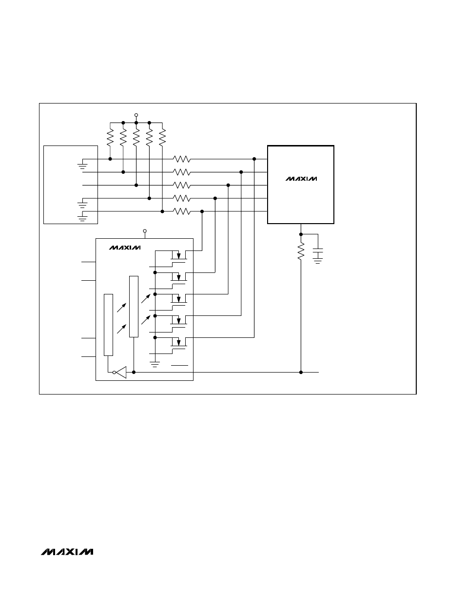
Figure 14. Using the ZMODE Multiplexer