Rainbow Electronics MAX1718 User Manual
Page 20
MAX1718
Notebook CPU Step-Down Controller for Intel
Mobile Voltage Positioning (IMVP-II)
20
______________________________________________________________________________________
low during Impedance mode must appear to be low
impedance, at least for the 4µs sampling interval.
This can be achieved in several ways, including the fol-
lowing two (Figure 13). By using low-impedance pullup
resistors with the CPU’s VID pins, each pin provides the
low impedance needed for the mux to correctly inter-
pret the Impedance mode setting. Unfortunately, the
low resistances cause several mA quiescent currents
for each of the CPU’s grounded VID pins. This quies-
cent current can be avoided by taking advantage of the
fact that D0–D4 need only appear low impedance
briefly, not necessarily on a continuous DC basis. High-
impedance pullups can be used if they are bypassed
with a large enough capacitance to make them appear
low impedance for the 4µs sampling interval. As noted
in Figure 13, 4.7nF capacitors allow the inputs to
appear low impedance even though they are pulled up
with large-value resistors. Each sampling depletes
some charge from the 4.7nF capacitors. A minimum
26k
Ω
D4
D3
D2
D1
D0
26k
Ω
26k
Ω
26k
Ω
26k
Ω
8k
Ω
100k
Ω
8k
Ω
8k
Ω
8k
Ω
8k
Ω
3.0V TO 5.5V
100k
Ω
+5V
B-DATA
LATCH
V
CC
GND
MAX1718
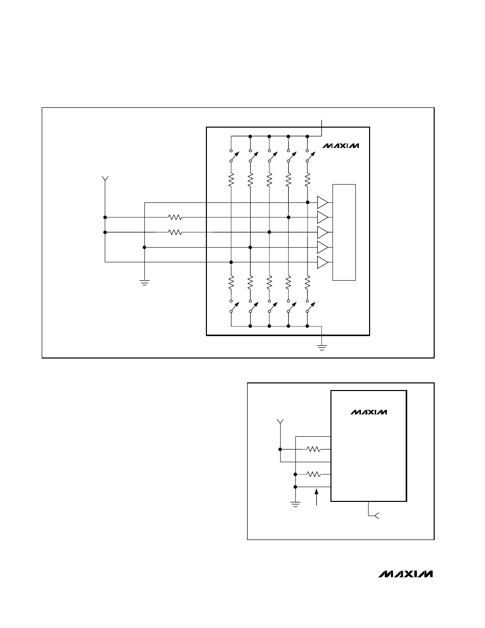
Figure 10. Internal Mux Impedance-Mode Data Test and Latch
MAX1718
D4
D3
D2
D1
D0
ZMODE
3.0V TO 5.5V
ZMODE HIGH
VID = 01010
1.25V
ZMODE LOW
VID = 01100
1.15V
100k
Ω
100k
Ω
ZMODE = HIGH = 1.25V
ZMODE = LOW = 1.15V
Figure 11. Using the Internal Mux with Hard-Wired Logic-Mode
and Impedance-Mode DAC Codes