Table 4. suspend mode dac codes – Rainbow Electronics MAX1718 User Manual
Page 19
MAX1718
Notebook CPU Step-Down Controller for Intel
Mobile Voltage Positioning (IMVP-II)
______________________________________________________________________________________
19
On the rising edge of ZMODE, during power-up with
ZMODE high or on the falling edge of SUS when
ZMODE is high, the impedances at D0–D4 are sampled
by the impedance decoder to see if a large resistance
is in series with the pin. This is called Impedance
mode. If the voltage level on the pin is a logic low, an
internal switch connects the pin to an internal 26k
Ω
pullup for about 4µs to see if the pin voltage can be
forced high (Figure 10). If the pin voltage can be pulled
to a logic high, the impedance is considered high and
so is the Impedance mode logic state. Similarly, if the
voltage level on the pin is a logic high, an internal
switch connects the pin to an internal 8k
Ω pulldown to
see if the pin voltage can be forced low. If so, the pin is
high impedance and its Impedance mode logic state is
high. In either sampling condition, if the pin’s logic level
does not change, the pin is determined to be low
impedance and the Impedance mode logic state is low.
A high pin impedance (and logic high) is 100k
Ω or
greater, and a low impedance (and logic low) is 1k
Ω or
less. The Electrical Characteristics table guaranteed
levels for these impedances are 95k
Ω and 1.05kΩ to
allow the use of standard 100k
Ω and 1kΩ resistors with
5% tolerance.
Using the ZMODE Mux
There are many ways to use the versatile ZMODE mux.
The preferred method will depend on when and how
the VID DAC codes for the various states are deter-
mined. If the output voltage codes are fixed at PC
board design time, program both codes with a simple
combination of pin-strap connections and series resis-
tors (Figure 11). If the output voltage codes are chosen
during PC board assembly, both codes can be inde-
pendently programmed with resistors (Figure 12). This
matrix of 10 resistor-footprints can be programmed to
all possible Logic mode and Impedance mode code
combinations with only 5 resistors.
Often the CPU pins provide one set of codes that are
typically used with pullup resistors to provide the Logic
mode VID code, and resistors in series with D0–D4 set
the Impedance mode code. Since some of the CPU’s
VID pins may float, the open-circuit pins can present a
problem for the ZMODE mux’s Impedance mode. For
the Impedance mode to work, any pins intended to be
S1
S0
OUTPUT VOLTAGE (V)
GND
GND
0.975
GND
REF
0.950
GND
OPEN
0.925
GND
V
CC
0.900
REF
GND
0.875
REF
REF
0.850
REF
OPEN
0.825
REF
V
CC
0.800
OPEN
GND
0.775
OPEN
REF
0.750
OPEN
OPEN
0.725
OPEN
V
CC
0.700
V
CC
GND
0.675
V
CC
REF
0.650
V
CC
OPEN
0.625
V
CC
V
CC
0.600
Table 4. Suspend Mode DAC Codes
D0
D1
D2
D3
D4
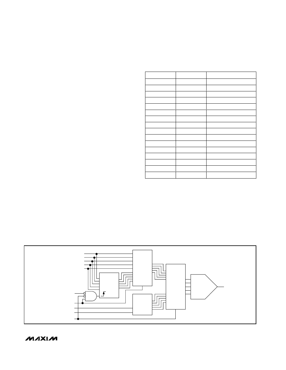
ZMODE
V
CC
POR
ZMODE MUX
S0/S1
DECODER
SEL
OUT
OUT
1
IN
IMPEDANCE
DECODER
IN
0
SUS MUX
SEL
OUT
DAC
1
0
S0
S1
SUS
Figure 9. Internal Multiplexers Functional Diagram