Rainbow Electronics MAX1718 User Manual
Page 22
MAX1718
Notebook CPU Step-Down Controller for Intel
Mobile Voltage Positioning (IMVP-II)
22
______________________________________________________________________________________
At the beginning of an output voltage transition, the
MAX1718 blanks the VGATE output, preventing it from
going low. VGATE remains blanked during the transi-
tion and is re-enabled when the slew-rate controller has
set the internal DAC to the final value and one addition-
al slew-rate clock period has passed. The slew-rate
clock frequency (set by resistor R
TIME
) must be set fast
enough to ensure that the longest required transition is
completed within the allowed 100µs.
The output voltage transition is performed in 25mV
steps, preceded by a delay and followed by one addi-
tional clock period. The total time for a transition
depends on R
TIME
, the voltage difference, and the
accuracy of the MAX1718’s slew-rate clock, and is not
dependent on the total output capacitance. The greater
the output capacitance, the higher the surge current
required for the transition. The MAX1718 will automati-
cally control the current to the minimum level required
to complete the transition in the calculated time, as long
as the surge current is less than the current limit set by
ILIM. The transition time is given by:
where f
SLEW
= 150kHz
✕
120k
Ω / R
TIME
, V
OLD
is the
original DAC setting, V
NEW
is the new DAC setting, and
T
DELAY
ranges from zero to a maximum of 2/f
SLEW
. See
Time Frequency Accuracy in the Electrical Charac-
teristics table for f
SLEW
accuracy.
The practical range of R
TIME
is 47k
Ω to 470kΩ, corre-
sponding to 2.6µs to 26µs per 25mV step. Although the
DAC takes discrete 25mV steps, the output filter makes
the transitions relatively smooth. The average inductor
current required to make an output voltage transition is:
I
L
≅ C
OUT
✕
25mV
✕
f
SLEW
Output Overvoltage Protection
The overvoltage protection (OVP) circuit is designed to
protect the CPU against a shorted high-side MOSFET
by drawing high current and blowing the battery fuse.
The output voltage is continuously monitored for over-
≤
×
−
+
1
25
f
V
V
mV
T
SLEW
OLD
NEW
DELAY
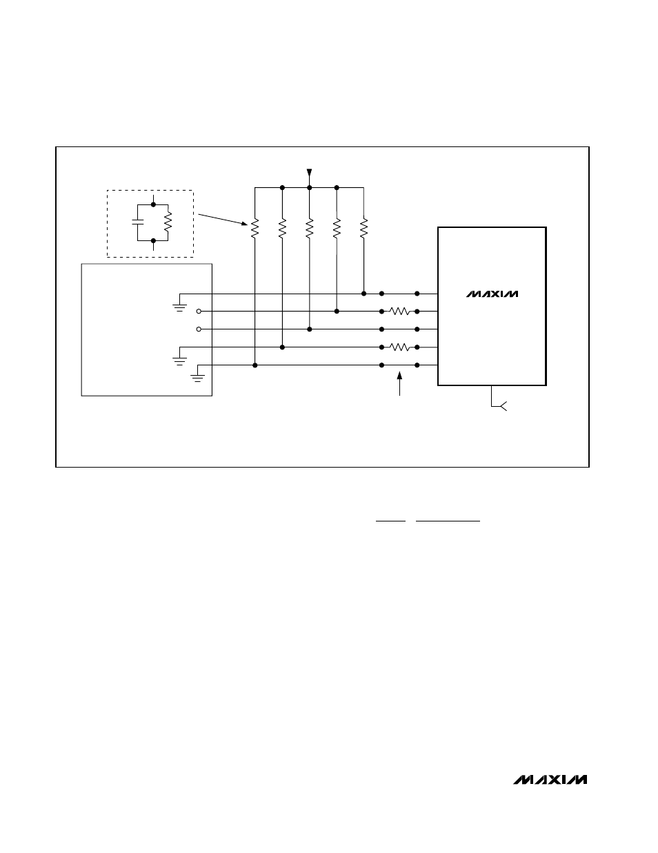
MAX1718
D4
D3
D2
D1
D0
ZMODE
*TO REDUCE QUIESCENT CURRENT, 1k
Ω PULLUP RESISTORS CAN BE REPLACED BY 1MΩ RESISTORS WITH 4.7nF CAPACATORS IN PARALLEL.
ZMODE HIGH
VID = 01010
→ 1.25V
CPU VID =
01100
→ 1.15V
(ZMODE LOW)
1k
Ω
1M
Ω
1k
Ω
1k
Ω
1k
Ω
1k
Ω
4.7nF
*OPTIONAL
3.15V TO 5.5V
100k
Ω
100k
Ω
CPU
ZMODE = HIGH = 1.25V
ZMODE = LOW = 1.15V
Figure 13. Using the Internal Mux with CPU Driving the Logic-Mode VID Code