Table 5. dac mux operation – Rainbow Electronics MAX1718 User Manual
Page 21
MAX1718
Notebook CPU Step-Down Controller for Intel
Mobile Voltage Positioning (IMVP-II)
______________________________________________________________________________________
21
interval of 2
✕
R
PULLUP
✕
4.7nF is recommended
between ZMODE samples.
In some cases, it is desirable to determine the
Impedance mode code during system boot so that sev-
eral processor types can be used without hardware
modifications. Figure 14 shows one way to implement
this function. The desired code is determined by the
system BIOS and programmed into one register of the
MAX1609 using the SMBus™ serial interface. The
MAX1609’s other register is left in its power-up state (all
outputs high impedance). When SMBSUS is low, the
outputs are high impedance and do not affect the
Logic-mode VID code setting. When SMBSUS is high,
the programmed register is selected, and the MAX1609
forces a low impedance on the appropriate VID input
pins. The ZMODE signal is delayed relative to the SMB-
SUS pin because the VID pins that are pulled low by
the MAX1609 take significant time to rise when they are
released. One additional benefit of using the MAX1609
for this application is that the application uses only five of
the MAX1609’s high-voltage, open-drain outputs. The
other three outputs can be used for other purposes.
Output Voltage Transition Timing
The MAX1718 is designed to perform output voltage
transitions in a controlled manner, automatically mini-
mizing input surge currents. This feature allows the cir-
cuit designer to achieve nearly ideal transitions,
guaranteeing just-in-time arrival at the new output volt-
age level with the lowest possible peak currents for a
given output capacitance. This makes the IC ideal for
IMVP-II CPUs.
IMVP-II CPUs operate at two distinct clock frequencies
and require three distinct VID settings. When transition-
ing from one clock frequency to the other, the CPU first
goes into a low-power state, then the output voltage
and clock frequency are changed. The change must
be accomplished in 100µs or the system may halt.
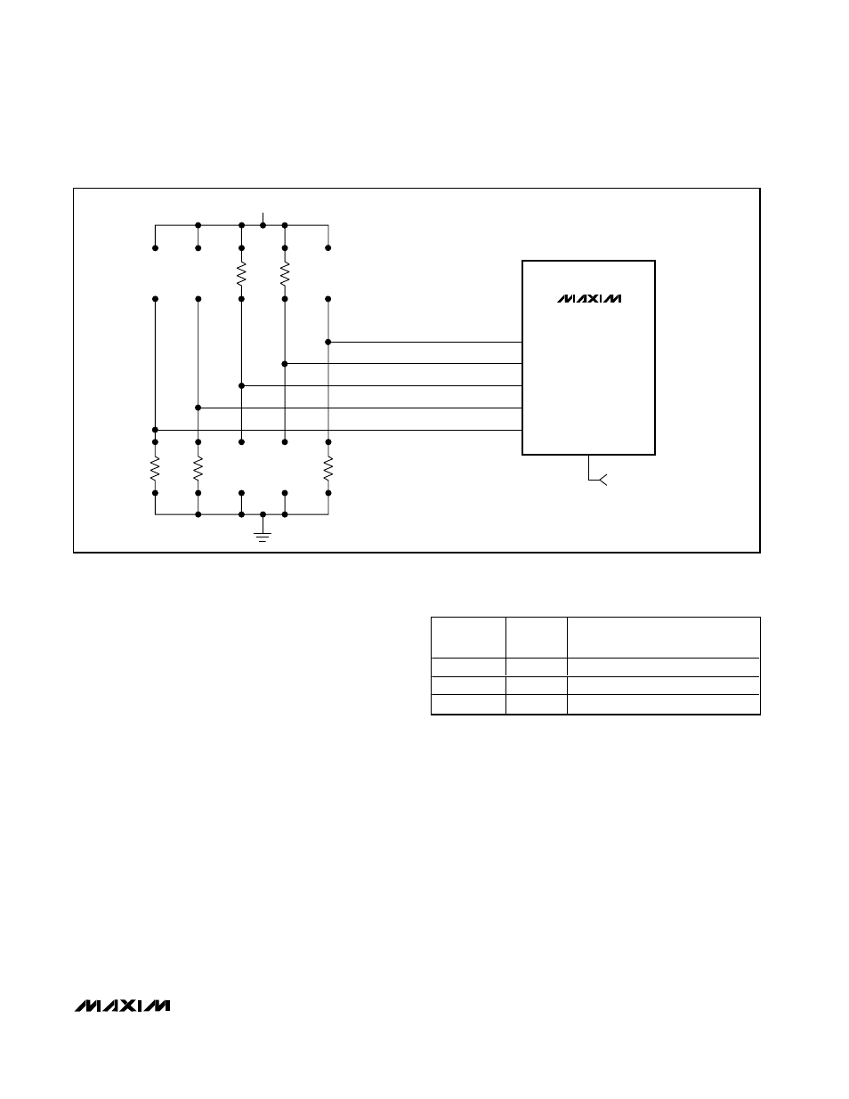
MAX1718
D4
D3
D2
D1
D0
ZMODE
ZMODE = HIGH = 1.25V
ZMODE = LOW = 1.15V
1k
Ω
1k
Ω
100k
Ω
1k
Ω
100k
Ω
2.7V TO 5.5V
NOTE: USE PULLUP FOR LOGIC MODE 1, PULLDOWN FOR LOGIC MODE 0.
USE
≥100kΩ FOR IMPEDANCE MODE 1, ≤1kΩ FOR IMPEDANCE MODE 0.
Figure 12. Using the Internal Mux with Both VID Codes Resistor Programmed
ZMODE
SUS
OUTPUT VOLTAGE
DETERMINED BY:
GND
GND
Logic Level of D0–D4
V
CC
GND
Impedance of D0–D4
X
V
CC
Logic Levels of S0, S1
Table 5. DAC Mux Operation
SMBus™ is a trademark of Intel Corp.