Loop-powered, 4–20ma transmitters, Wire and 4-wire rtd configurations – Rainbow Electronics MAX1403 User Manual
Page 34
MAX1403
+3V, 18-Bit, Low-Power, Multichannel,
Oversampling (Sigma-Delta) ADC
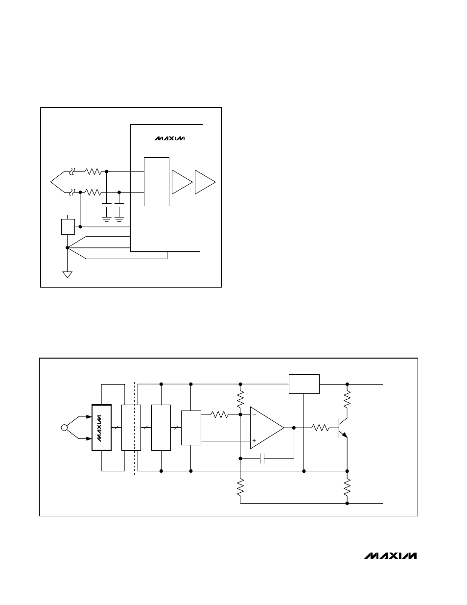
Loop-Powered, 4–20mA Transmitters
Low-power, single-supply operation, and easy interfac-
ing with optocouplers make the MAX1403 ideal for
loop-powered 4–20mA transmitters. Loop-powered
transmitters draw their power from the 4–20mA loop,
limiting the transmitter circuitry to a current budget of
4mA. Tolerances in the loop further limit this current
budget to 3.5mA. Since the MAX1403 consumes only
250µA, a total of 3.25mA remains to power the remain-
ing transmitter circuitry. Figure 16 shows a block dia-
gram for a loop-powered 4–20mA transmitter.
3-Wire and 4-Wire RTD Configurations
Tightly matched 200µA current sources compensate for
errors in 3-wire and 4-wire RTD configurations. In the 3-
wire configuration (Figure 17), the lead resistances
result in errors if only one current source is used. The
200µA will flow through R
L1
developing a voltage error
between AIN1 and AIN2. An additional current source
compensates for this error by developing an equivalent
voltage across R
L2
, ensuring the differential voltage at
AIN1 and AIN2 is not affected by lead resistance. This
assumes both leads are of the same material and of
equal length (R
L1
= R
L2
), and assumes OUT1 and
OUT2 have matching tempcos (5ppm/°C). Both current
sources will flow through R
L3
, developing a common-
mode voltage that will not affect the differential voltage
at AIN1 and AIN2. Using one of the current sources to
supply the reference voltage ensures a more accurate
ratiometric result.
DAC
R
GAIN
R
OFST
R
X
V
IN+
V
IN-
R
SENSE
4–20mA LOOP
INTERFACE
R
FDBK
R
Y
C
C
ISOLATION
BARRIER
V+
GND
V+
4
SPI
4
SPI
3
SPI
GND
SENSOR
VOLTAGE
REGULATOR
µ
P/
µ
C
MAX1403
Figure 16. 4–20mA Transmitter
C
C
+3V
+1.25V
REFIN+
REFIN-
AGND
DGND
R
R
THERMOCOUPLE
JUNCTION
SWITCHING
NETWORK
PGA
MAX1403
BUFFER
AIN1
AIN2
Figure 15. Thermocouple Application with MAX1403
34
______________________________________________________________________________________