Rainbow Electronics MAX1403 User Manual
Page 32
MAX1403
+3V, 18-Bit, Low-Power, Multichannel,
Oversampling (Sigma-Delta) ADC
32
______________________________________________________________________________________
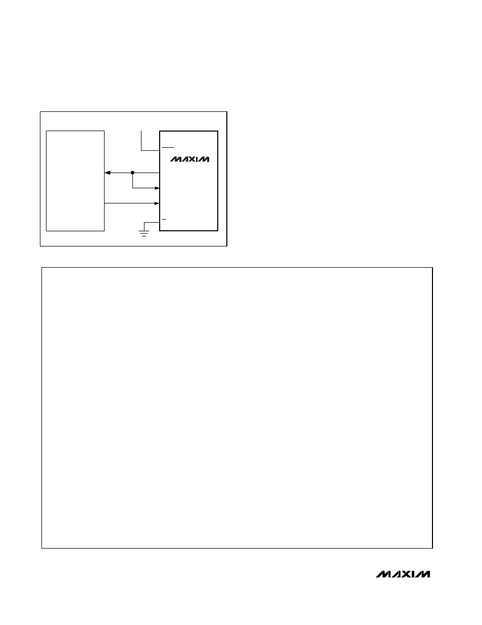
Bit-Banging Interface (80C51, PIC16C54)
Any microcontroller can use general-purpose I/O pins
to interface to the MAX1403. If a bidirectional or open-
drain I/O pin is available, reduce the interface pin count
by connecting DIN to DOUT (Figure 13). Listing 2
shows how to emulate the SPI in software. Use the
same initialization routine shown in Listing 1.
For best results, use a hardware interrupt to monitor the
INT pin and acquire new data as soon as it is available.
If hardware interrupts are not available, or if interrupt
latency is longer than the selected conversion rate, use
the FSYNC bit to prevent automatic measurement while
reading the data output register.
/* Low-level function to write 8 bits
** The example shown here is for a bit-banging system with (CPOL=1, CPHA=1)
*/
void WriteByte (BYTE x)
{
drive SCK pin high
count = 0;
while (cout <= 7)
{
if (bit 7 of x is 1)
drive DIN pin high
else
drive DIN pin low
drive SCK pin low
x = x * 2;
drive SCK pin high
count = count + 1;
}
}
/* Low-level function to read 8 bits
** The example shown here is for a bit-banging system with (CPOL=1, CPHA=1)
*/
BYTE ReadByte (void)
{
x = 0;
drive SCK pin high
count = 0;
while (cout <= 7)
{
x = x * 2;
drive SCK pin low
if (DOUT pin is high)
x = x + 1;
drive SCK pin high
count = count + 1;
}
}
return x;
Listing 2. Bit-Banging SPI Replacement
V
DD
P3.0
P3.1
RESET
DOUT
DIN
SCLK
CS
8051
MAX1403
Figure 13. MAX1403 to 8051 Interface