Table 13a. r – Rainbow Electronics MAX1403 User Manual
Page 23
Transducer Excitation Currents
The MAX1403 provides two matched 200µA transducer
excitation currents at OUT1 and OUT2. These currents
have low absolute temperature coefficients and tight
TC matching. These characteristics enable accurate
compensation of errors due to IR drops in long trans-
ducer cable runs. They may be enabled or disabled
using a single register control bit (IOUT).
Dynamic Input Impedance at the
Channel Selection Network
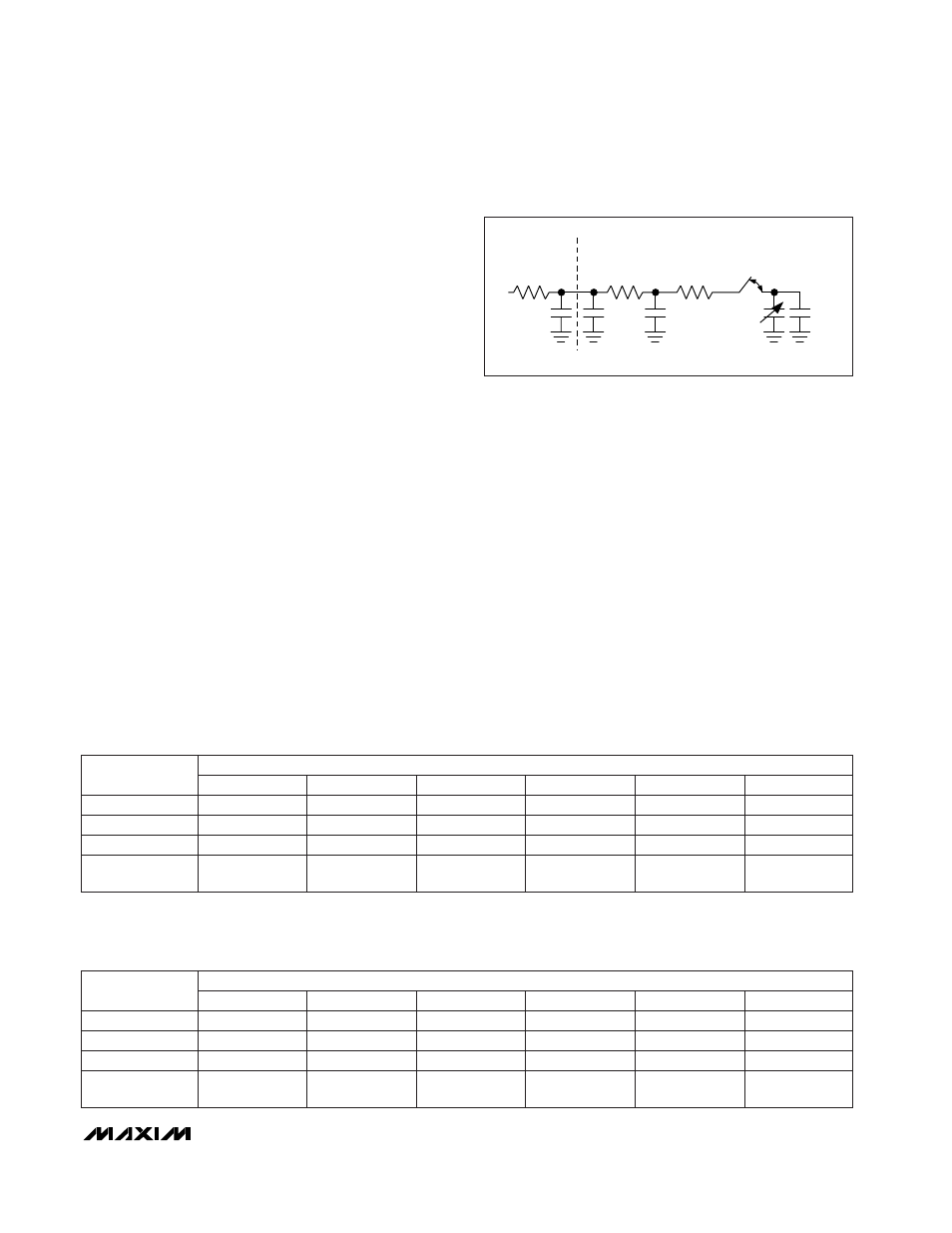
When used in unbuffered mode (BUFF = 0), the analog
inputs present a dynamic load to the driving circuitry.
The size of the sampling capacitor and the input sam-
pling frequency (Figure 5) determine the dynamic load
seen by the driving circuitry. The MAX1403 samples at a
constant rate for all gain settings. This provides a maxi-
mum time for the input to settle at a given data rate. The
dynamic load presented by the inputs varies with the
gain setting. For gains of +2V/V, +4V/V, and +8V/V, the
input sampling capacitor increases with the chosen
gain. Gains of +16V/V, +32V/V, +64V/V, and +128V/V
present the same input load as the x8 gain setting.
When designing with the MAX1403, as with any other
switched-capacitor ADC input, consider the advantages
and disadvantages of series input resistance. A series
resistor reduces the transient-current impulse to the
external driving amplifier. This improves the amplifier
phase margin and reduces the possibility of ringing.
The resistor spreads the transient-load current from the
sampler over time due to the RC time constant of the
circuit. However, an improperly chosen series resis-
tance can hinder performance in fast 16-bit converters.
The settling time of the RC network can limit the speed
at which the converter can operate properly, or reduce
the settling accuracy of the sampler. In practice, this
means ensuring that the RC time constant—resulting
from the product of the driving source impedance and
the capacitance presented by both the MAX1403’s
input and any external capacitances—is sufficiently
small to allow settling to the desired accuracy. Tables
13a–13d summarize the maximum allowable series
resistance vs. external capacitance for each MAX1403
gain setting in order to ensure 16-bit performance in
unbuffered mode.
MAX1403
+3V, 18-Bit, Low-Power, Multichannel,
Oversampling (Sigma-Delta) ADC
______________________________________________________________________________________
23
R
EXT
C
EXT
R
MUX
C
PIN
R
SW
C
ST
C
SAMPLE
C
C
Figure 5. Analog Input, Unbuffered Mode (BUFF = 0)
Table 13a. R
EXT
, C
EXT
Values for Less than 16-Bit Gain Error in Unbuffered (BUFF = 0)
Mode—1x Modulator Sampling Frequency (MF1, MF0 = 00); X2CLK = 0; CLKIN = 2.4576MHz
Table 13b. R
EXT
, C
EXT
Values for Less than 16-Bit Gain Error in Unbuffered (BUFF = 0)
Mode—2x Modulator Sampling Frequency (MF1, MF0 = 01); X2CLK = 0; CLKIN =
2.4576MHz
34
15
34
15
9.8
2
25
13
17
10
7.3
8, 16, 32,
64, 128
8.7
9.8
4
1
C
EXT
= 0pF
C
EXT
= 50pF
C
EXT
= 100pF
2.9
1.6
2.9
1.6
0.43
2.7
1.5
2.4
1.4
0.37
0.40
PGA GAIN
0.43
C
EXT
= 500pF
C
EXT
= 1000pF
C
EXT
= 5000pF
EXTERNAL RESISTANCE, R
EXT
(k
Ω
)
17
7.5
17
7.5
4.9
2
13
6.4
8.4
5.0
3.7
8, 16, 32,
64, 128
4.4
4.9
4
1
C
EXT
= 0pF
C
EXT
= 50pF
C
EXT
= 100pF
1.4
0.81
1.4
0.81
0.22
1.3
0.76
1.2
0.70
0.18
0.20
PGA GAIN
0.22
C
EXT
= 500pF
C
EXT
= 1000pF
C
EXT
= 5000pF
EXTERNAL RESISTANCE, R
EXT
(k
Ω
)