Max1870a step-up/step-down li+ battery charger, Table 4. component list – Rainbow Electronics MAX1870A User Manual
Page 27
MAX1870A
Step-Up/Step-Down
Li+ Battery Charger
______________________________________________________________________________________
27
MOSFET Power Dissipation
Table 5 shows the resistive losses and switching losses
in each of the MOSFETs during either step-up or step-
down operation. Table 5 provides a first-order estimate,
but does not consider second-order effects such as
ripple current or nonlinear gate drive.
For typical applications where V
BATT
/ 2 < V
IN
< 2 x
V
BATT
, the resistive losses are primarily dissipated in M1
since M2 operates at a lower duty cycle. Switching loss-
es are dissipated in M1 when in step-down mode and in
M2 when in step-up mode. Ratio the MOSFETs so that
resistive losses roughly equal switching losses when at
maximum load and typical input/output conditions. The
resistive loss equations are a good approximation in
hybrid mode (V
IN
near V
BATT
). Both M1 and M2 switch-
ing losses apply in hybrid mode.
Switching losses can become a heat problem when the
maximum AC adapter voltage is applied in step-down
operation or minimum AC adapter voltage is applied
with a maximum battery voltage. This behavior occurs
because of the squared term in the CV
2
f switching-loss
equation. Table 5 provides only an estimate and is not
a substitute for breadboard evaluation.
Inductor Selection
Select the inductor to minimize power dissipation in the
MOSFETs, inductor, and sense resistors. To optimize
resistive losses and RMS inductor current, set the LIR
(inductor current ripple) to 0.3. Because the maximum
resistive power loss occurs at the step-up boundary of
hybrid mode, select LIR for operating in this mode. Select
the inductance according to the following equation:
Larger inductance values can be used; however, they
contribute extra resistance that can reduce efficiency.
Smaller inductance values increase RMS currents and
can also reduce efficiency.
Saturation Current Rating
The inductor must have a saturation current rating high
enough so it does not saturate at full charge, maximum
output voltage, and minimum input voltage. In step-up
operation, the inductor carries a higher current than in
step-down operation with the same load. Calculate the
inductor saturation current rating by the following
equation:
Input-Capacitor Selection
The input capacitor must meet the ripple current
requirement (I
RMS
) imposed by the switching currents.
Nontantalum chemistries (ceramic, aluminum, or OS-
I
SAT
≥
V
OUT_ MAX
x I
CHG_ MAX
V
IN _MIN
+
T x V
IN _ MIN
x 1 −
V
IN _MIN
V
OUT_MAX
2 x L
L
x V
x t
LIR I
IN
CHG
=
2
min
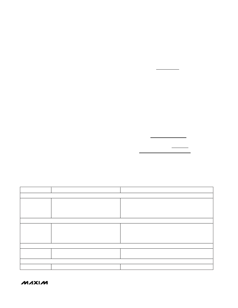
Table 4. Component List
DESIGNATION
PART NUMBER
SPECIFICATIONS
INDUCTORS
L1
Sumida CDRH104R-100
Sumida CDRH104R-7R0
Sumida CDRH104R-5R2
Sumida CDRH104R-3R8
10µH, 4.4A, 35m
Ω
power inductor
7µH, 4.8A, 27m
Ω
power inductor
5.2µH, 5.5A, 22m
Ω
power inductor
3.8µH, 6A, 13m
Ω
power inductor
P-CHANNEL MOSFETs
M1
Siliconix Si4435DY
Fairchild FDC602P
Fairchild FDS4435A
Fairchild FDW256P
P-FET 35m
Ω
, Q
G
= 17nC, V
DSMAX
= 30V, 8-pin SO
P-FET 35m
Ω
, Q
G
= 14nC, V
DSMAX
= 20V, 6-pin SuperSOT
P-FET 25m
Ω
, Q
G
= 21nC, V
DSMAX
= 30V, 8-pin SO
P-FET 20m
Ω
, Q
G
= 28nC, V
DSMAX
= 30V, 8-pin TSSOP
N/P-CHANNEL MOSFET PAIRS
M1/M2
Fairchild FDW2520C (8-pin TSSOP)
N-FET 18m
Ω
, Q
G
= 14nC, V
DSMAX
= 20V,
P-FET 35m
Ω
, Q
G
= 14nC, V
DSMAX
= 20V
N-CHANNEL MOSFETs
M2
IRF7811W
N-FET, 9m
Ω
, Q
G
= 18nC, V
DSMAX
= 30V, 8-pin SO