Max1870a step-up/step-down li+ battery charger, Detailed description, Table 1. cell-count programming table – Rainbow Electronics MAX1870A User Manual
Page 16
MAX1870A
Step-Up/Step-Down
Li+ Battery Charger
16
______________________________________________________________________________________
Detailed Description
The MAX1870A includes all of the functions necessary
to charge Li+, NiMH, and NiCd batteries. A high-effi-
ciency H-bridge topology DC-DC converter controls
charge voltage and current. A proprietary control
scheme offers improved efficiency and smaller inductor
size compared to conventional H-bridge controllers and
operates from input voltages above and below the bat-
tery voltage. The MAX1870A includes analog control
inputs to limit the AC adapter current, charge current,
and battery voltage. An analog output (IINP) delivers a
current proportional to the source current. The Typical
Application Circuit shown in Figure 1 uses a microcon-
troller (µC) to control the charge current or voltage,
while Figure 2 shows a typical application with the
charge voltage and current fixed to specific values for
the application. The voltage at ICTL and the value of
RS2 set the charge current. The voltage at VCTL and
the CELLS inputs set the battery regulation voltage for
the charger. The voltage at CLS and the value of R3 and
R4 set the source current limit.
The MAX1870A features a voltage-regulation loop
(CCV) and two current-regulation loops (CCI and CCS).
CCV is the compensation point for the battery voltage
regulation loop. CCI and CCS are the compensation
points for the battery charge current and supply current
loops, respectively. The MAX1870A regulates the
adapter current by reducing battery charge current
according to system load demands.
Setting the Charge Voltage
The MAX1870A provides high-accuracy regulation of
the charge voltage. Apply a voltage to VCTL to adjust
the battery-cell voltage limit. Set VCTL to a voltage
between 0 and V
REFIN
for a 10% adjustment of the bat-
tery cell voltage, or connect VCTL to LDO for a default
setting of 4.2V per cell. The limited adjustment range
reduces the sensitivity of the charge voltage to external
resistor tolerances. The overall accuracy of the charge
voltage is better than ±1% when using ±1% resistors to
divide down the reference to establish VCTL. The per-
cell battery-termination voltage is a function of the bat-
tery chemistry and construction. Consult the battery
manufacturer to determine this voltage. Calculate bat-
tery voltage using the following equation:
where N
CELLS
is the cell count selected by CELLS.
VCTL is ratiometric with respect to REFIN to improve
accuracy when using resistive voltage-dividers.
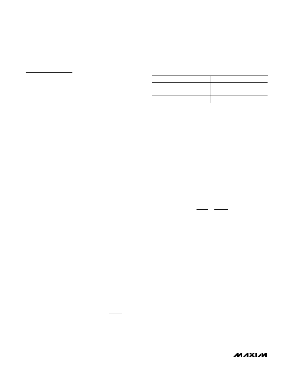
Connect CELLS as shown in Table 1 to charge two,
three, or four cells. The cell count can either be hard-
wired or software controlled. The internal error amplifier
(GMV) maintains voltage regulation (see Figure 3 for
the Functional Diagram). Connect a 10kΩ resistor in
series with a 0.01µF capacitor from CCV to GND to
compensate the battery voltage loop. See the Voltage
Loop Compensation section for more information.
Setting the Charge Current
Set the maximum charge current using ICTL and the
current-sense resistor RS2 connected between CSIP
and CSIN. The current threshold is set by the ratio of
V
ICTL
/ V
REFIN
. Use the following equation to program
the battery charge current:
where V
CSIT
is the full-scale charge current-sense
threshold, 73mV (typ). The input range for ICTL is
V
REFIN
/ 32 to V
REFIN
. To shut down the MAX1870A,
force ICTL below V
REFIN
/ 100.
The internal error amplifier (GMI) maintains charge-
current regulation (see Figure 3 for the Functional
Diagram). Connect a 0.01µF capacitor from CCI to GND
to compensate the charge-current loop. See the Charge-
Current Loop Compensation section for more information.
Setting the Input Current Limit
The total input current, from a wall adapter or other DC
source, is a function of the system supply current and
the battery charge current. The MAX1870A limits the wall
adapter current by reducing the charge current when the
input current exceeds the input current-limit set point. As
the system supply current rises, the available charge
current decreases linearly to zero in proportion to the
system current. After the charge current has fallen to
zero, the MAX1870A cannot further limit the wall adapter
current if the system current continues to increase.
I
V
R
x
V
V
CHG
CSIT
S
ICTL
REFIN
=
2
V
N
x
V
V x
V
V
BATT
CELLS
VCTL
REFIN
=
+
4
0 4
.
Table 1. Cell-Count Programming Table
CELLS
CELL COUNT
GND
2
Float
3
REFIN
4