Max1870a step-up/step-down li+ battery charger – Rainbow Electronics MAX1870A User Manual
Page 20
MAX1870A
Step-Up/Step-Down
Li+ Battery Charger
20
______________________________________________________________________________________
up operation. During this mode, the MAX1870A regu-
lates the step-up on-time. Initially DBST switches M2 on
(state C) and the inductor current ramps up with a dI/dt
of V
IN
/ L. After the inductor current crosses the target
current (set by the error integrators), DBST switches M2
off (state B) and the inductor current ramps down with
a dI/dt of (V
BATT
- V
IN
) / L. M2 remains off until a step-
up off-time timer expires. This off-time is calculated
based on the input and output voltage to maintain
400kHz pseudo-fixed-frequency operation. The step-up
on-time is regulated by the error signal, set according
to the charge current or source current if either is at its
limit, or the battery voltage if both charge current and
source current are below their respective current limits.
Step-Up/Step-Down Operation
(0.9 x V
BATT
< V
IN
< 1.4 x V
BATT
)
The MAX1870A features a step-up/step-down mode
that eliminates dropout. Figure 8 shows the inductor
current in step-up/step-down operation. When V
IN
is
within 10% of V
BATT
, the MAX1870A alternates through
states A, B, and C, following the order A, B, C, B, A, B,
C, etc., with the majority of the time spent in state B.
Since more time is spent in state B, the inductor ripple
current is reduced, improving efficiency.
The time in state C is peak-current regulated, and the
remaining time is spent in state B (Figure 8A). During
this operating mode, the average inductor current is
approximately 20% higher than the load current.
The time in state A is valley current and the remaining
time is spent in state B (Figure 8B). During this mode,
the average inductor current is approximately 10%
higher than the load current.
Alternative algorithms require inductor currents twice
as high, resulting in four times larger I
2
R losses and
inductors typically four times larger in volume.
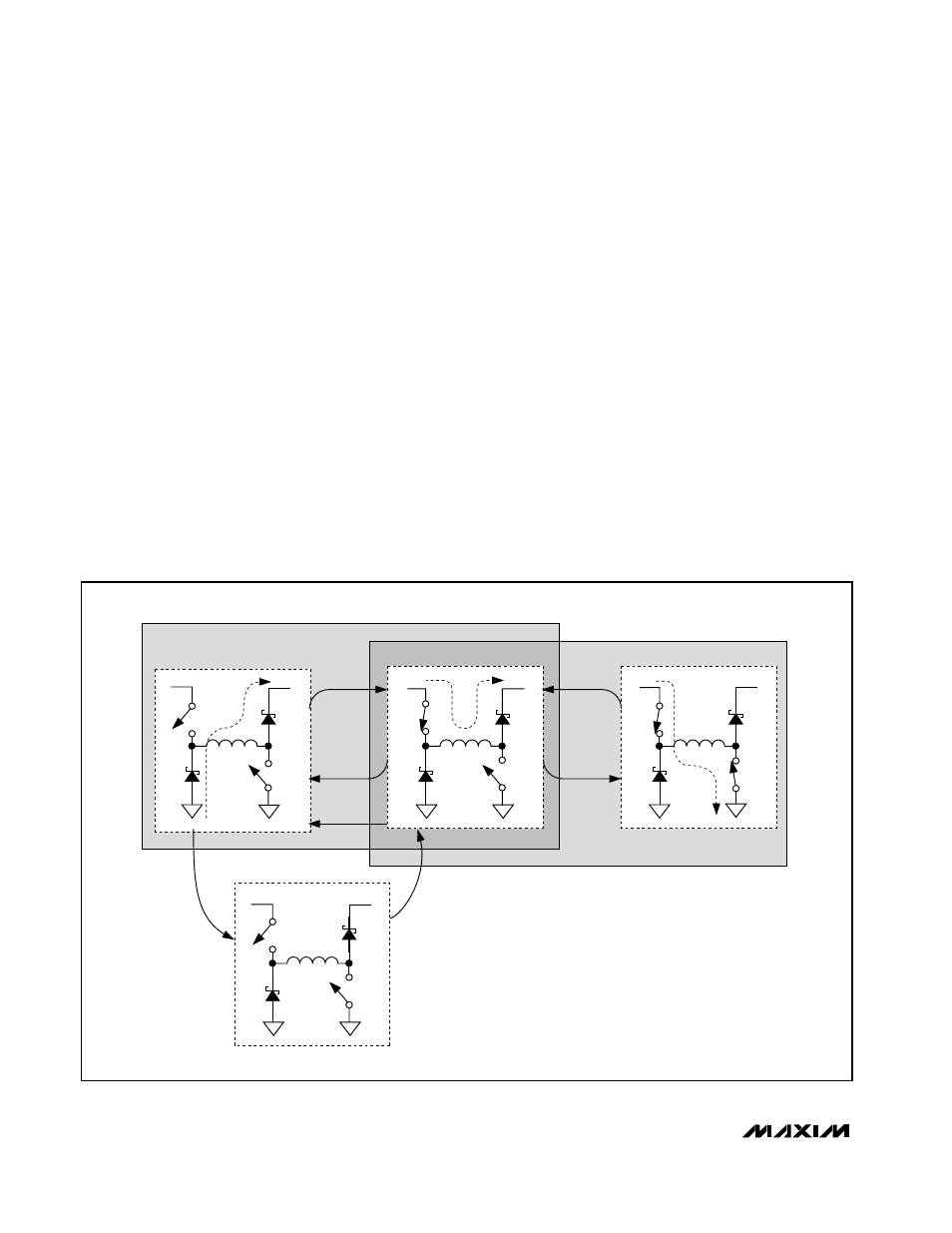
IMIN, IMAX, CCMP, and ZCMP
The MAX1870A state machine utilizes five comparators
to decide which state to be in and when to switch
states (Figure 3). The MAX1870A generates an error
V
IN
V
OUT
M1
D3
D4
M2
STEP-DOWN OFF
V
IN
V
OUT
M1
M2
STEP-DOWN ON
STATE B
STATE A
STATE C
V
IN
V
OUT
M1
M2
STEP-DOWN PFM
IDLE STATE D
V
IN
V
OUT
M1
M2
+
-
STEP-DOWN
PWM
STEP-UP
PWM
STEP-UP OFF
STEP-UP ON
D4
D2
D4
D3
D3
D3
Figure 5. MAX1870A State Machine