Max1870a step-up/step-down li+ battery charger, Pin description (continued) – Rainbow Electronics MAX1870A User Manual
Page 13
MAX1870A
Step-Up/Step-Down
Li+ Battery Charger
______________________________________________________________________________________
13
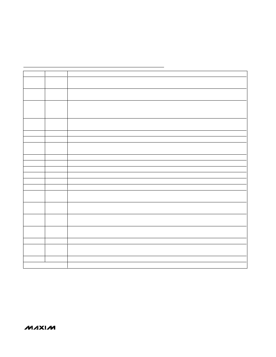
Pin Description (continued)
PIN
NAME
FUNCTION
12
ICTL
Charge-Current Control Input. Drive ICTL from V
REFIN
/ 32 to V
REFIN
to adjust the charge current. See the
Setting the Charge Current section. Drive ICTL to GND to disable charging.
13
CELLS
Cell-Count Selection Input. Connect CELLS
to GND for two Li+ cells. Float CELLS for three Li+ cells, or
connect CELLS
to REFIN for four Li+ cells.
14
IINP
Input-Current Monitor Output. IINP is a replica of the input current sensed by the MAX1870. It represents
the sum of the current consumed by the charger and the current consumed by the system. IINP has a
transconductance of 2.8µA/mV.
15
SHDN
Shutdown Comparator Input. Pull SHDN low to stop charging. Optionally connect a thermistor to stop
charging when the battery temperature is too hot.
16
BATT
Battery-Voltage Feedback Input
17
CSIN
Charge Current-Sense Negative Input
18
CSIP
Charge Current-Sense Positive Input. Connect a current-sense resistor from CSIP to CSIN. Connect a
2.2µF capacitor from CSIP to GND.
19
BLKP
Power Connection for Current-Sense Amplifier. Connect BLKP to BATT.
20, 21
I.C.
Internally Connected. Do not connect this pin.
22
DBST
Step-Up Power MOSFET (NMOS) Gate-Driver Output
23
PGND
Power Ground
24
I.C.
Internally Connected. Do not connect this pin.
25
DLOV
Low-Side Driver Supply. Bypass DLOV with a 1µF capacitor to GND.
26
VHN
Power Connection for the High-Side MOSFET Driver. Bypass VHP to VHN with a 1µF or greater ceramic
capacitor.
27
DHI
High-Side Power MOSFET (PMOS) Driver Output. Connect to the gate of the high-side step-down
MOSFET.
28
VHP
Power Connection for the High-Side MOSFET Driver. Bypass VHP to VHN with a 1µF or greater ceramic
capacitor.
29
CSSN
Negative Terminal for Current-Sense Resistor for Charger Current. Connect a 2.2µF capacitor from CSSN
to GND.
30
CSSS
Negative Terminal for Current-Sense Resistor for System Load Current
31
CSSP
Positive Terminal for Input Current-Sense Resistors. Connect a current-sense resistor from CSSP to
CSSN. Connect an equivalent sense resistor from CSSP to CSSS.
32
DCIN
DC Supply Voltage Input. Bypass DCIN with a 1µF or greater ceramic capacitor to power ground.
Paddle
Paddle. Connect to GND.