Max1870a step-up/step-down li+ battery charger – Rainbow Electronics MAX1870A User Manual
Page 22
MAX1870A
Step-Up/Step-Down
Li+ Battery Charger
22
______________________________________________________________________________________
point, LVC, to the inductor current. In step-down mode,
the off-time (state A) is terminated when the inductor
current falls below the current threshold set by LVC. In
step-up mode, the on-time (state C) is terminated when
the inductor current rises above the current threshold
set by LVC.
IMAX: The IMAX comparators provide a cycle-by-cycle
inductor current limit. This circuit compares the induc-
tor current (CSI in step-down mode or CSS in step-up
mode) to the internally fixed cycle-by-cycle current
limit. The current-sense voltage limit is 200mV. With
RS1_ = RS2 = 30mΩ, which corresponds to 6.7A. If the
inductor current-sense voltage is greater than V
IMAX
(200mV), a step-up on-time is terminated or a step-
down on-time is not permitted.
ZCMP: The ZCMP comparator detects when the induc-
tor current crosses zero. If the ZCMP output goes high
during a step-down off-time, the MAX1870A switches to
the idle state (state D) to conserve power.
Switching Frequency
The MAX1870A includes input and output-voltage feed-
forward to maintain pseudo-fixed-frequency (400kHz)
operation. The time in state B is set according to the
input voltage, output voltage, and a time constant. In
step-up/step-down mode the switching frequency is
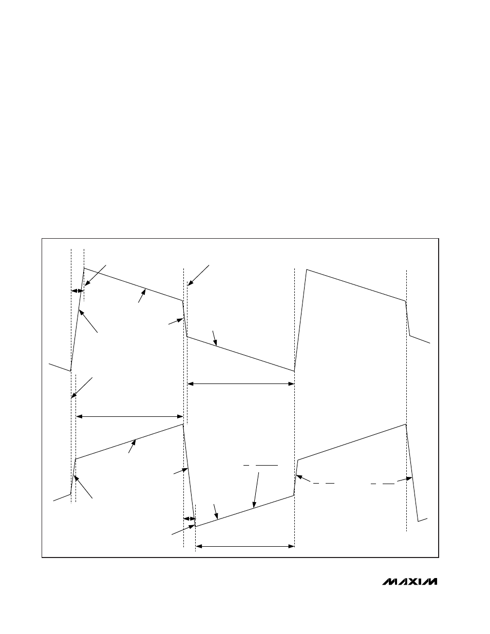
STATE C
STATE B
STATE A
STATE B
STATE A
STATE B
STATE C
STATE B
A)
B)
MINIMUM
STEP-DOWN
OFF-TIME
PRECALCULATED STEP-UP
OFF-TIME
PRECALCULATED STEP-DOWN
ON-TIME
PRECALCULATED STEP-DOWN
ON-TIME
MINIMUM
STEP-UP
ON-TIME
PEAK REGULATED
STEP-UP
ON-TIME
VALLEY REGULATED
STEP-DOWN
OFF-TIME
dl
dt
V
BATT
- V
IN
L
=
dl
dt
V
IN
L
=
dl
dt
V
BATT
L
=
Figure 8. MAX1870A Step-Up/Step-Down Inductor-Current Waveform