Max1870a step-up/step-down li+ battery charger – Rainbow Electronics MAX1870A User Manual
Page 19
MAX1870A
Step-Up/Step-Down
Li+ Battery Charger
______________________________________________________________________________________
19
• Continuous output current for V
IN
> 1.4 x V
OUT
reduces output ripple.
The MAX1870A uses the state machine shown in Figure
5. The controller switches between the states A, B, and C,
depending on V
IN
and V
BATT
. State D provides PFM
operation during light loads. Under moderate and heavy
loads the MAX1870A operates in PWM.
Step-Down Operation
(V
IN
> 1.4 x V
BATT
)
During medium and heavy loads when V
IN
> 1.4 x
V
BATT
, the MAX1870A alternates between state A and
state B, keeping MOSFET M2 off (Figure 5). Figure 6
shows the inductor current in step-down operation.
During this mode, the MAX1870A regulates the step-
down off-time. Initially, DHI switches M1 off (state A) and
the inductor current ramps down with a dI/dt of V
BATT
/ L
until a target current is reached (determined by the error
integrator). After the target current is reached, DHI
switches M1 on (state B), and the inductor current ramps
up with a dI/dt of (V
IN
- V
BATT
) / L. M1 remains on until a
step-down on-time timer expires. This on-time is calculat-
ed based on the input and output voltage to maintain
pseudo-fixed-frequency 400kHz operation. At the end of
state B, another step-down off-time (state A) is initiated
and the cycle repeats. The off-time is valley regulated
according to the error signal. The error signal is set by
the charge current or source current if either is at its limit,
or the battery voltage if both charge current and source
current are below their respective current limits.
During light loads, when the inductor current falls to
zero during state A, the controller switches to state D to
reduce power consumption and avoid shuttling current
in and out of the output.
Step-Up Operation (V
IN
< 0.9 x V
BATT
)
When V
IN
< 0.9 x V
BATT
, the MAX1870A alternates
between state B and state C, keeping MOSFET M1 on.
In this mode, the controller looks like a simple step-up
controller. Figure 7 shows the inductor current in step-
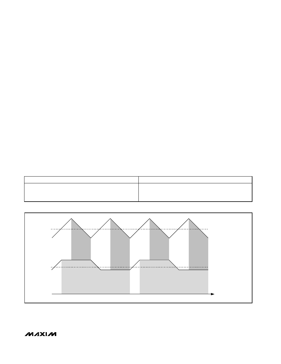
A) CONVENTIONAL
ALGORITHM
B) MAX1870A
ALGORITHM
2 x I
CHARGE
SHADED REGIONS REPRESENT
CHARGE DELIVERED
TIME
Figure 4. Inductor Current for V
IN
= V
BATT
Table 2. MAX1870A H-Bridge Controller Advantages
MAX1870A H-BRIDGE CONTROLLER
TRADITIONAL H-BRIDGE CONTROLLER
•
Only 1 MOSFET switched per cycle
•
Continuous output current in step-down mode
•
2 MOSFETs switched per cycle
•
Always discontinuous output current
(requires higher inductor currents)