Max1870a step-up/step-down li+ battery charger – Rainbow Electronics MAX1870A User Manual
Page 23
MAX1870A
Step-Up/Step-Down
Li+ Battery Charger
______________________________________________________________________________________
23
effectively cut in half to allow for both the step-up cycle
and the step-down cycle. The switching frequency is
typically between 350kHz and 405kHz for V
IN
between
8V and 28V. See the Typical Operating Characteristics.
Compensation
Each of the three regulation loops (the battery voltage,
the charge current, and the input current limit) are com-
pensated separately using the CCV, CCI, and CCS
pins, respectively. Compensate the voltage regulation
loop with a 10kΩ resistor in series with a 0.01µF capaci-
tor from CCV to GND. Compensate the charge current
loop and source current loop with 0.01µF capacitors
from CCI to GND and from CCS to GND, respectively.
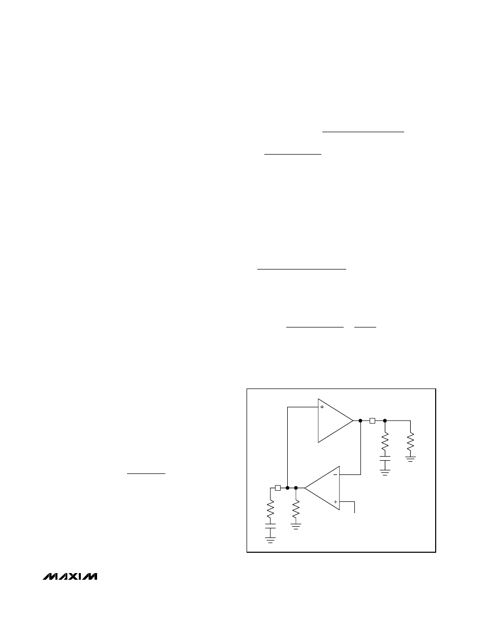
Voltage Loop Compensation
When regulating the charge voltage, the MAX1870A
behaves as a current-mode step-down or step-up
power supply. Since a current-mode controller regulates
its output current as a function of the error signal, the
duty-cycle modulator can be modeled as a GM stage
(Figure 9). Results are similar in step-down, step-up, or
step-up/down, with the exception of a load-dependent
right-half-plane zero that occurs in step-up mode.
The required compensation network is a pole-zero pair
formed with C
CV
and R
CV
. C
CV
is chosen to be large
enough that its impedance is relatively small compared
to R
CV
at frequencies near crossover. R
CV
sets the
gain of the error amplifier near crossover. R
CV
and
C
OUT
determine the crossover frequency and, there-
fore, the closed-loop response of the system and the
response time upon battery removal.
R
ESR
is the equivalent series resistance (ESR) of the
charger’s output capacitor (C
OUT
). R
L
is the equivalent
charger output load, R
L
= ∆V
BATT
/ ∆I
CHG
= R
BATT
.
The equivalent output impedance of the GMV amplifier,
R
OGMV
, is greater than 10MΩ. The voltage loop
transconductance (GMV = ∆I
CCV
/ ∆V
BATT
) scales
inversely with the number of cells. GMV = 0.1µA/mV for
four cells, 0.133µA/mV for three cells, and 0.2µA/mV for
two cells. The DC-DC converter’s transconductance
depends upon the charge current-sense resistor RS2:
where A
CSI
= 18, and RS2 = 30mΩ in the Typical
Application Circuits, so GM
PWM
= 1.85A/V.
Use the following equation to calculate the loop transfer
function (LTF):
The poles and zeros of the voltage-loop transfer func-
tion are listed from lowest frequency to highest frequen-
cy in Table 3.
Near crossover, C
CV
has much lower impedance than
R
OGMV
. Since C
CV
is in parallel with R
OGMV,
C
CV
dom-
inates the parallel impedance near crossover.
Additionally, R
CV
has a much higher impedance than
C
CV
and dominates the series combination of R
CV
and
C
CV
, so:
C
OUT
also has a much lower impedance than R
L
near
crossover, so the parallel impedance is mostly capaci-
tive and:
If R
ESR
is small enough, its associated output zero has
a negligible effect near crossover and the loop transfer
function can be simplified as follows:
R
sC
x R
sC
L
OUT
L
OUT
(
)
1
1
+
≅
R
x
sC
x R
sC
x R
R
near crossover
OGMV
CV
CV
CV
OGMV
CV
(
)
(
)
,
1
1
+
+
≅
LTF
GM
x
R
x
sC
R
sC
x R
x
R
sC
x R
x G
x
sC
x R
PWM
OGMV
CV
CV
CV
OGMV
L
OUT
L
MV
OUT
ESR
=
+
+
+
+
(
)
(
)
(
)
(
)
1
1
1
1
GM
A
x RS
PWM
CSI
=
1
2
GM
OUT
REF
GMV
R
L
R
ESR
C
OUT
R
O
R
CV
C
CV
BATT
CCV
Figure 9. CCV Simplified Loop Diagram