Applications information – Rainbow Electronics ADC1175-50 User Manual
Page 14
Applications Information
(All Schematic
pin numbers refer to the TSSOP.) (Continued)
remedy. The solution is to keep the analog circuitry well
separated from the digital circuitry and from the digital
ground plane.
Digital circuits create substantial supply and ground current
transients. The logic noise thus generated could have sig-
nificant impact upon system noise performance. The best
logic family to use in systems with A/D converters is one
which employs non-saturating transistor designs, or has low
noise characteristics, such as the 74HC(T) and 74AC(T)Q
families. The worst noise generators are logic families that
draw the largest supply current transients during clock or
signal edges, like the 74F and the 74AC(T) families. In
general, slower logic families, such as 74LS and 74HC(T)
will produce less high frequency noise than do high speed
logic families, such as the 74F and 74AC(T) families.
Since digital switching transients are composed largely of
high frequency components, total ground plane copper
weight will have little effect upon the logic-generated noise.
This is because of the skin effect. Total surface area is more
important than is total ground plane volume.
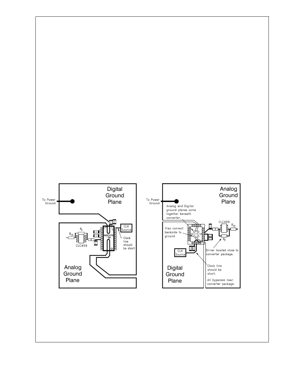
An effective way to control ground noise is by connecting the
analog and digital ground planes together beneath the ADC
with a copper trace that is very narrow (about 1/16 inch)
compared with the rest of the ground plane. This narrowing
beneath the converter provides a fairly high impedance to
the high frequency components of the digital switching cur-
rents, directing them away from the analog pins. The rela-
tively lower frequency analog ground currents do not see a
significant impedance across this narrow ground connection.
The back of the LLP package has a large metal area inside
the area bounded by the pins. This metal area is connected
to the die substrate (ground). This pad may be left floating if
desired. If it is connected to anything, it should be to ground
near the connection between analog and digital ground
planes. Soldering this metal pad to ground will help keep the
die cooler and could yield improved performance because of
the lower impedance between die and board grounds. How-
ever, a poor layout could compromise performance.
Generally, analog and digital lines should cross each other at
90˚ to avoid getting digital noise into the analog path. In high
frequency systems, however, avoid crossing analog and
digital lines altogether. Clock lines should be isolated from
ALL other lines, analog AND digital. Even the generally
accepted 90˚ crossing should be avoided as even a little
coupling can cause problems at high frequencies. Best per-
formance at high frequencies and at high resolution is ob-
tained with a straight signal path.
Be especially careful with the layout of inductors. Mutual
inductance can change the characteristics of the circuit in
which they are used. Inductors should not be placed side by
side with each other, not even with just a small part of their
bodies beside each other.
The analog input should be isolated from noisy signal traces
to avoid coupling of spurious signals into the input. Any
external component (e.g., a filter capacitor) connected be-
tween the converter’s input and ground should be connected
to a very clean point in the analog ground plane.
Figure 6 gives an example of a suitable layout. All analog
circuitry (input amplifiers, filters, reference components, etc.)
should be placed on or over the analog ground plane. All
digital circuitry and I/O lines should be placed over the digital
ground plane.
7.0 DYNAMIC PERFORMANCE
The ADC1175-50 is ac tested and its dynamic performance
is guaranteed. To meet the published specifications, the
clock source driving the CLK input must be free of jitter. For
best ac performance, isolating the ADC clock from any digital
circuitry should be done with adequate buffers, as with a
clock tree. See
Figure 7.
DS100896-28
FIGURE 6. Layout Examples Showing Separate Analog and Digital Ground Planes Connected below the ADC1175-50
ADC1
175-50
www.national.com
14