Ata6832 – Rainbow Electronics ATA6832 User Manual
Page 5
5
4951A–AUTO–08/06
ATA6832
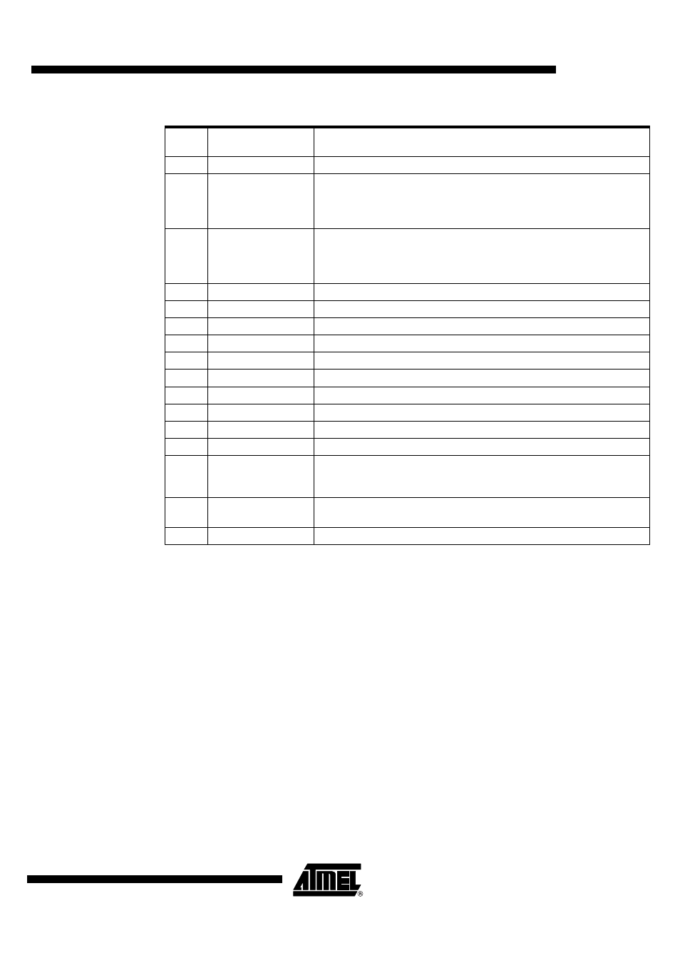
Table 3-2.
Output Data Protocol
Bit
Output (Status)
Register
Function
0
TP
Temperature prewarning: high = warning
1
Status LS1
Normal operation: high = output is on, low = output is off
Open-load detection: high = open load, low = no open load
(correct load condition is detected if the corresponding output is
switched off); not affected by SRR
2
Status HS1
Normal operation: high = output is on, low = output is off
Open-load detection: high = open load, low = no open load
(correct load condition is detected if the corresponding output is
switched off); not affected by SRR
3
Status LS2
Description see LS1
4
Status HS2
Description see HS1
5
Status LS3
Description see LS1
6
Status HS3
Description see HS1
7
n. u.
Not used
8
n. u.
Not used
9
n. u.
Not used
10
n. u.
Not used
11
n. u.
Not used
12
n. u.
Not used
13
OVL
Over-load detected: set high, when at least one output is switched off
by a short-circuit condition or an overtemperature event. Bits 1 to 6 can
be used to detect the affected switch
14
INH
Inhibit: this bit is controlled by software (bit SI in input register)
High = standby, low = normal operation
15
PSF
Power-supply fail: undervoltage at pin VS detected