Atf22v10c(q), Compiler mode selection, Dc characteristics – Rainbow Electronics ATF22V10CQ User Manual
Page 3
3
ATF22V10C(Q)
0735P–PLD–01/02
Note:
1. These device types will create a JEDEC file which when programmed in ATF22V10C devices will enable the power-down
mode feature. All other device types have the feature disabled.
Note:
1. Not more than one output at a time should be shorted. Duration of short circuit test should not exceed 30 sec.
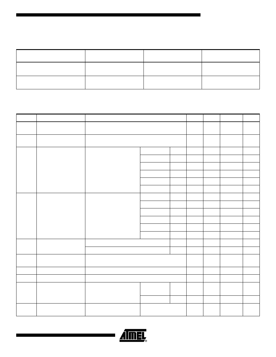
Compiler Mode Selection
PAL Mode
(5828 Fuses)
GAL Mode
(5892 Fuses)
Power-down Mode
(5893 Fuses)
Synario
ATF22V10C (DIP)
ATF22V10C (PLCC)
ATTF22V10C DIP (UES)
ATF22C10C PLCC (UES)
ATF22V10C DIP (PWD)
ATF22V10C PLCC (PWD)
WINCUPL
P22V10
P22V10LCC
G22V10
G22V10LCC
G22V10CP
G22V10CPLCC
DC Characteristics
Symbol
Parameter
Condition
Min
Typ
Max
Units
I
IL
Input or I/O Low
Leakage Current
0
≤ V
IN
≤ V
IL
(Max)
-35.0
-10.0
µA
I
IH
Input or I/O High
Leakage Current
3.5
≤ V
IN
≤ V
CC
10.0
µA
I
CC
Power Supply Current,
Standby
V
CC
= Max,
V
IN
= Max,
Outputs Open
C-5, 7, 10
Com.
85.0
130.0
mA
C-10
Ind.
90.0
140.0
mA
C-15
Com.
65.0
90.0
mA
C-15
Ind.
65.0
115.0
mA
CQ-15
Com.
35.0
55.0
mA
CQ-15
Ind.
35.0
70.0
mA
I
CC2
Clocked Power Supply
Current
V
CC
= Max, Outputs Open,
f = 15 MHz
C-5, 7, 10
Com.
150.0
mA
C-10
Ind.
160.0
mA
C-15
Com.
70.0
90.0
mA
C-15
Ind.
70.0
90.0
mA
CQ-15
Com.
40.0
60.0
mA
CQ-15
Ind.
40.0
80.0
mA
I
PD
Power Supply Current,
PD Mode
V
CC
= Max
Com.
10.0
100.0
µA
V
IN
= 0, Max
Ind.
10.0
100.0
µA
I
OS
Output Short Circuit
Current
V
OUT
= 0.5V
-130.0
mA
V
IL
Input Low Voltage
-0.5
0.8
V
V
IH
Input High Voltage
2.0
V
CC
+0.75
V
V
OL
Output Low Voltage
V
IN
= V
IH
or V
IL
,
V
CC
= Min
I
OL
= 16 mA
Com.,
Ind.
0.5
V
I
OL
= 12 mA
Mil.
0.5
V
V
OH
Output High Voltage
V
IN
= V
IH
or V
IL
,
V
CC
= Min
I
OH
= -4.0 mA
2.4
V