As shown in – Rainbow Electronics AT42QT1110-AZ User Manual
Page 14
14
9570H–AT42–02/10
AT42QT1110-MZ/AT42QT1110-AZ
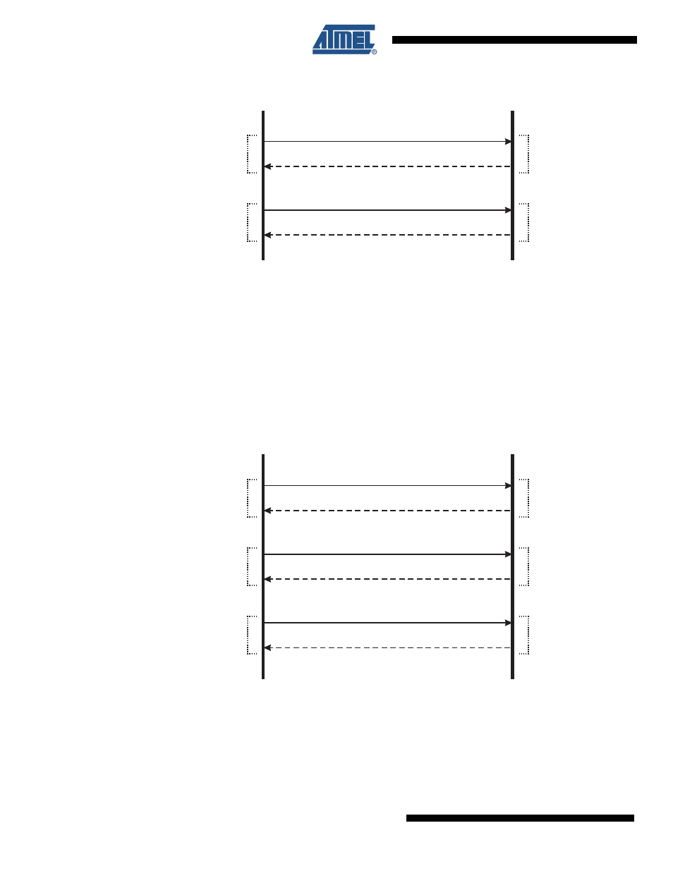
Figure 4-5.
Positive Recalibration Delay Set Instruction – CRC Disabled
With CRC Enabled, a CRC byte is also required (
). This is calculated for the two
transmitted bytes (that is, the “Set” command and the data byte).
For example, for the sequence shown in
(0x95 — 0x0C), the CRC Byte is 0x9F. As is
the case with the other command types, when the QT1110 is expecting a CRC byte from the
host, it calculates that byte in advance and returns the expected value to the host in the same
transmission as the host sends the CRC byte.
The sent data is not applied to the memory location until the CRC byte has been received and
verified.
Figure 4-6.
Positive Recalibration Delay Set Instruction – CRC Enabled
Host (Sends on MOSI)
Command: 0x95
“Set” Data: 0x0C
Response: 0x95 (Command Just Received)
Simultaneous
Transmission
Response: 0x55 ( Idle”
Fresh Command)
“
–
Device (Responds on MISO)
Host (Sends on MOSI)
Command: 0x95
“Set” Data: 0x0C
Response: 0x95 (Command Just Received)
Simultaneous
Transmission
Command CRC: 0x9F
Response: 0x9F (Expected CRC)
Response: 0x55 ( Idle”
Fresh Command)
“
–
Device (Responds on MISO)