Typical operating circuit description, Operation – Rainbow Electronics DS1687 User Manual
Page 3
DS1685/DS1687
3 of 38
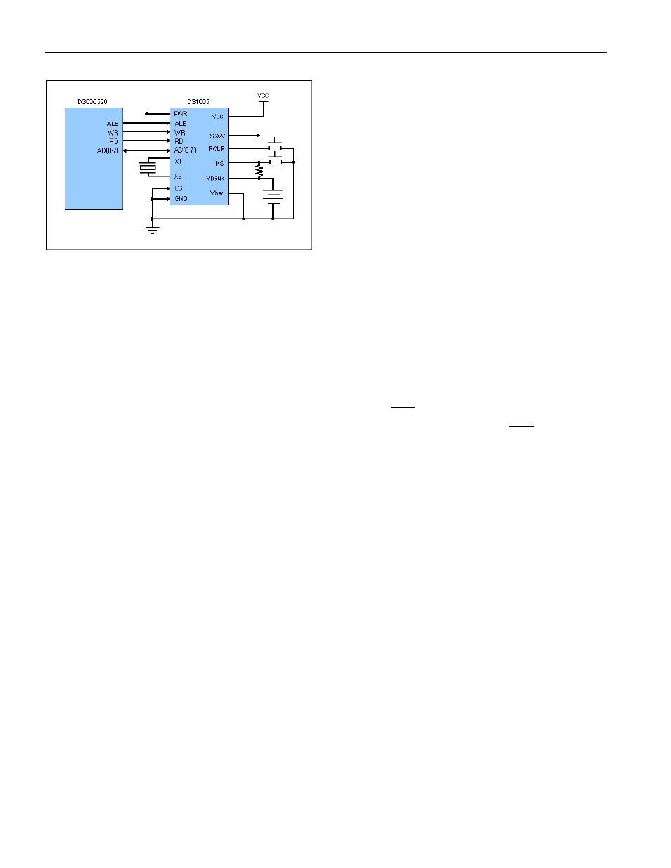
TYPICAL OPERATING CIRCUIT
DESCRIPTION
The DS1685/DS1687 is a real-time clock (RTC) designed as a successor to the industry-standard
DS1285, DS1385, DS1485, and DS1585 PC RTCs. This device provides the industry-standard DS1285
clock function with either +3.0V or +5.0V operation. The DS1685 also incorporates a number of
enhanced features including a silicon serial number, power-on/off control circuitry, 242 bytes of user NV
SRAM, and 32.768kHz output for sustaining power management activities.
The DS1685/DS1687 power-control circuitry allows the system to be powered on by an external stimulus
such as a keyboard or by a time and date (wake-up) alarm. The
PWR
output pin can be triggered by one
or either of these events, and can be used to turn on an external power supply. The
PWR
pin is under
software control, so that when a task is complete, the system power can then be shut down.
The DS1685 is a clock/calendar chip with the features described above. An external crystal and battery
are the only components required to maintain time-of-day and memory status in the absence of power.
The DS1687 incorporates the DS1685 chip, a 32.768kHz crystal, and a lithium battery in a complete,
self-contained timekeeping module. The entire unit is fully tested at Dallas Semiconductor such that a
minimum of 10 years of timekeeping and data retention in the absence of V
CC
is guaranteed.
OPERATION
The block diagram in Figure 1 shows the pin connections with the major internal functions of the
DS1685/DS1687. The following paragraphs describe the function of each pin.