Ac electrical characteristics – Rainbow Electronics DS1858 User Manual
Page 4
DS1858
Dual Temperature-Controlled Resistors with
Three Monitors
4
_____________________________________________________________________
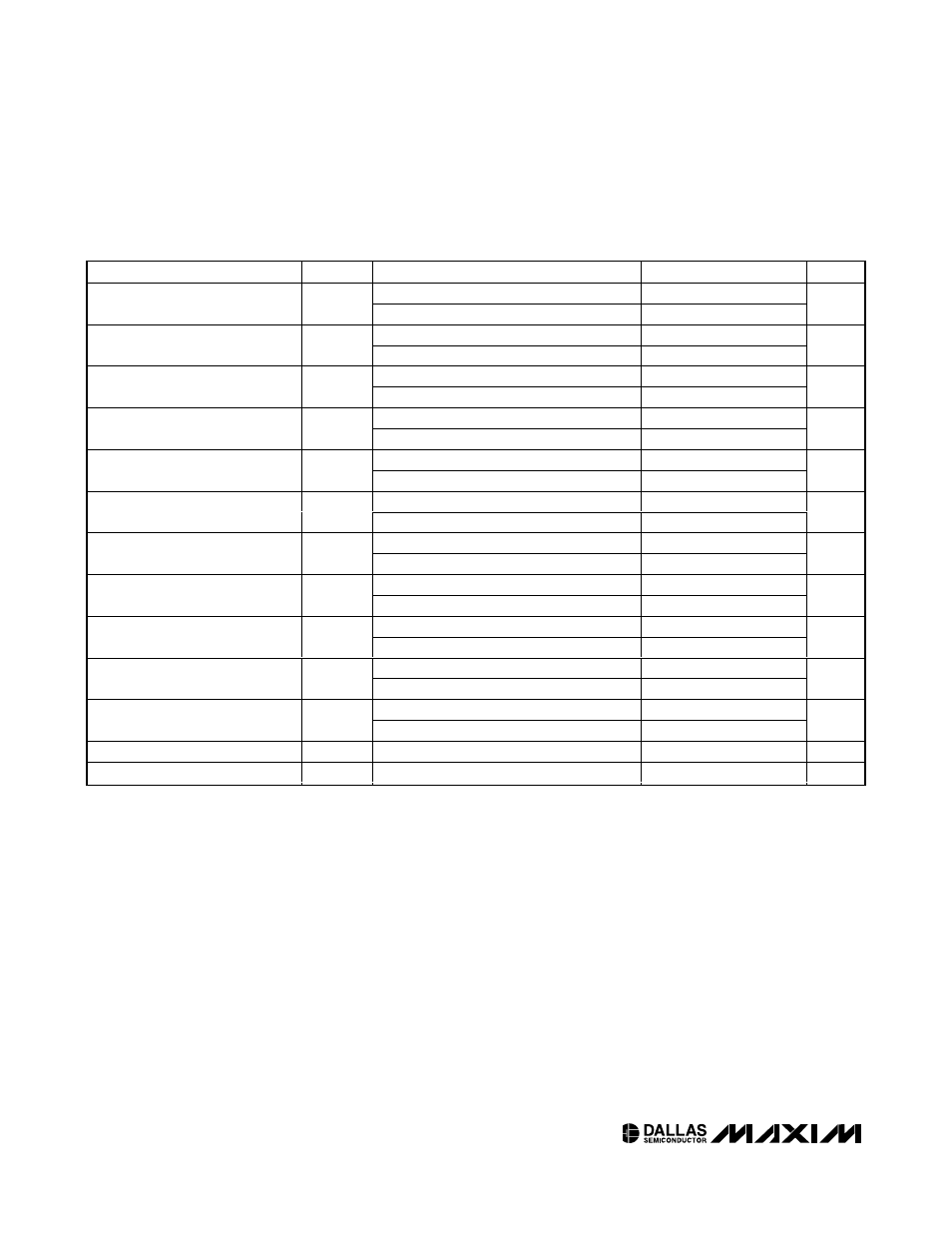
PARAMETER
SYMBOL
CONDITIONS
MIN
TYP
MAX
UNITS
Fast mode (Note 9)
0
400
SCL Clock Frequency
f
SCL
Standard mode (Note 9)
0
100
kHz
Fast mode (Note 9)
1.3
Bus Free Time Between STOP and
START Condition
t
BUF
Standard mode (Note 9)
4.7
µs
Fast mode (Notes 9, 10)
0.6
Hold Time (Repeated)
START Condition
t
HD:STA
Standard mode (Notes 9, 10)
4.0
µs
Fast mode (Note 9)
1.3
Low Period of SCL Clock
t
LOW
Standard mode (Note 9)
4.7
µs
Fast mode (Note 9)
0.6
High Period of SCL Clock
t
HIGH
Standard mode (Note 9)
4.0
µs
Fast mode (Notes 9, 11, 12)
0
0.9
Data Hold Time
t
HD:DAT
Standard mode (Notes 9, 11, 12)
0
µs
Fast mode (Note 9)
100
Data Setup Time
t
SU:DAT
Standard mode (Note 9)
250
ns
Fast mode (Note 9)
0.6
Start Setup Time
t
SU:STA
Standard mode (Note 9)
4.7
µs
Fast mode (Note 13)
20 + 0.1C
B
300
Rise Time of Both SDA and SCL
Signals
t
R
Standard mode (Note 13)
20 + 0.1C
B
1000
ns
Fast mode (Note 13)
20 + 0.1C
B
300
Fall Time of Both SDA and SCL
Signals
t
F
Standard mode (Note 13)
20 + 0.1C
B
300
ns
Fast mode
0.6
Setup Time for STOP Condition
t
SU:STO
Standard mode
4.0
µs
Capacitive Load for Each Bus Line
C
B
(Note 13)
400
pF
EEPROM Write Time
t
W
(Note 14)
10
ms
AC ELECTRICAL CHARACTERISTICS
(V
CC
= 3.0V to 5.5V, T
A
= -40°C to +95°C, unless otherwise noted.)
Note 1:
All voltages are referenced to ground.
Note 2: I/O pins of fast-mode devices must not obstruct the SDA and SCL lines if V
CC
is switched off.
Note 3:
SDA and SCL are connected to V
CC
and all other input signals are connected to well-defined logic levels.
Note 4: The maximum voltage the MON inputs will read is approximately 2.5V, even if the voltage on the inputs is greater than 2.5V.
Note 5:
This voltage is defining the maximum range of the analog-to-digital converter voltage and not the maximum V
CC
voltage.
Note 6: Absolute linearity is the difference of measured value from expected value at DAC position. The expected value is a
straight line from measured minimum position to measured maximum position.
Note 7: Relative linearity is the deviation of an LSB DAC setting change vs. the expected LSB change. The expected LSB change
is the slope of the straight line from measured minimum position to measured maximum position.
Note 8: See the
Typical Operating Characteristics.
Note 9: A fast-mode device can be used in a standard-mode system, but the requirement t
SU:DAT
> 250ns must then be met. This
is automatically the case if the device does not stretch the LOW period of the SCL signal. If such a device does stretch the
LOW period of the SCL signal, it must output the next data bit to the SDA line t
RMAX
+ t
SU:DAT
= 1000ns + 250ns = 1250ns
before the SCL line is released.