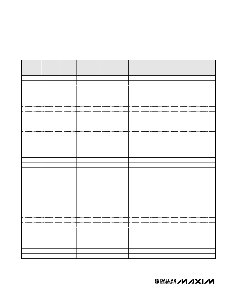
Table 01h – Rainbow Electronics DS1858 User Manual
Page 16
DS1858
Dual Temperature-Controlled Resistors with
Three Monitors
MEMORY
LOCATION
(hex)
EEPROM/
SRAM
R/W
DEFAULT
SETTING
(hex)
NAME OF
LOCATION
FUNCTION
80
SRAM
R/W
Mode
—
Bit 7
—
—
0
X
—
6
—
—
0
X
—
5
—
—
0
X
—
4
—
—
0
X
—
3
—
—
0
X
—
2
—
—
0
X
—
1
—
—
1
TEN
If TEN = 0, the temperature conversions update and the
resistors can be controlled manually. The user sets the
resistor in manual mode by writing to addresses 82h and
83h in Table 01 to control resistors 0 and 1, respectively.
0
—
—
1
AEN
AEN = 0 provides manual control of the temperature
index.
81
SRAM
R
—
Temp index
This byte is the temperature-calculated index used to
select the address of resistor settings in the look-up
tables.
82
SRAM
R/W
00
Resistor 0
Resistor 0 position values from 00h to FFh.
83
SRAM
R/W
00
Resistor 1
Resistor 1 position values from 00h to FFh.
84 to 87
SRAM
—
00
Reserved
—
88
EEPROM
R/W
Interrupt enable
This byte configures a maskable interrupt, determining
which event asserts a buffer 1 output (MINT set to 1, see
register 89h in Table 01). If any combination of
temperature, V
CC
, MON1, MON2, or MON3 is desired to
generate an interrupt, the corresponding bits are set to 1.
If interrupt generation is not desired, set all bits to 0.
Bit 7
—
—
1
TMP
—
6
—
—
1
V
CC
—
5
—
—
1
MON1
—
4
—
—
1
MON2
—
3
—
—
1
MON3
—
2
—
—
0
X
—
1
—
—
0
X
—
0
—
—
0
X
—
89
EEPROM
R/W
Configuration
—
Bit 7
—
—
0
X
—
6
—
—
0
X
Table 01h
16
____________________________________________________________________