Chip topology – Rainbow Electronics DS1858 User Manual
Page 21
devices on the bus is to be accessed. When read-
ing or writing the DS1858, the device-select bits
must match one of two valid device addresses,
00h or the address registered in
Table
01 location
8Ch. The last bit of the command/control byte
(R/W) defines the operation to be performed.
When set to a ‘1’ a read operation is selected, and
when set to a ‘0’ a write operation is selected. The
slave address can be set by the EEPROM.
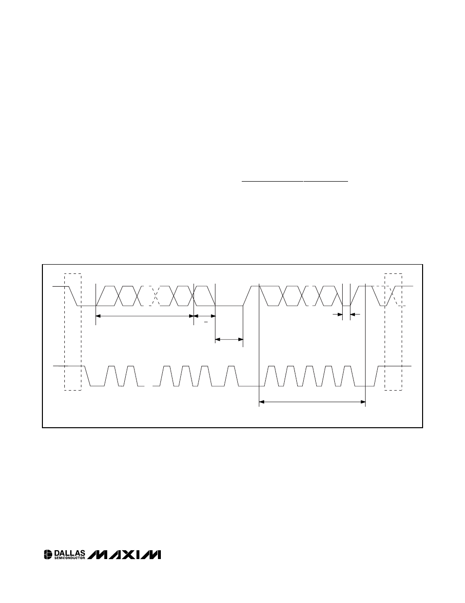
Following the start condition, the DS1858 monitors the
SDA bus checking the device type identifier being
transmitted. Upon receiving the 1010 control code, the
appropriate device address bits, and the read/write bit,
the slave device outputs an acknowledge signal on the
SDA line.
DS1858
Dual Temperature-Controlled Resistors with
Three Monitors
____________________________________________________________________
21
Chip Topology
TRANSISTOR COUNT: 44149
SUBSTRATE CONNECTED TO GROUND
STOP
CONDITION
OR REPEATED
START
CONDITION
REPEATED IF MORE BYTES
ARE TRANSFERRED
ACK
START
CONDITION
ACK
ACKNOWLEDGEMENT
SIGNAL FROM RECEIVER
ACKNOWLEDGEMENT
SIGNAL FROM RECEIVER
SLAVE ADDRESS
MSB
SCL
SDA
R/W
DIRECTION
BIT
1
2
6
7
8
9
1
2
8
9
3–7
Figure 5. 2-Wire Data Transfer Protocol